
If you have spent any time learning electronics, you have probably come across the term MOSFET. It stands for Metal-Oxide-Semiconductor Field-Effect Transistor — and while that sounds intimidating, the idea behind it is surprisingly straightforward. MOSFETs are the backbone of modern electronics: they switch your motor drivers, regulate power supplies, control LED strips, and are literally inside every processor you have ever used.
This guide strips away the jargon and explains MOSFET basics in plain language — what they are, how N-Channel and P-Channel types differ, when to use each, and how to get them working in your own circuits.
What Is a MOSFET?
A MOSFET is a type of transistor that uses an electric field — controlled by voltage — to switch or amplify electronic signals. Unlike a BJT (Bipolar Junction Transistor) which is current-controlled, a MOSFET is voltage-controlled. This makes it extremely efficient because the control signal draws almost no current.
MOSFETs come in two major flavours based on the majority charge carrier:
- N-Channel MOSFET — conducts when gate voltage is positive relative to the source
- P-Channel MOSFET — conducts when gate voltage is negative relative to the source
Within each type, there are also Enhancement Mode (normally off — the most common type for switching) and Depletion Mode (normally on) variants. For hobby and industrial switching applications, enhancement mode is what you will almost always use.
The Three Terminals: Gate, Drain, Source
Every MOSFET has three pins:
- Gate (G): The control terminal. Applying voltage here opens or closes the switch. It draws almost zero current because it is isolated from the channel by a thin oxide layer — this is the MOS part of MOSFET.
- Drain (D): Where current flows in (for N-Channel). In a switching application, the load is typically connected between the supply rail and the drain.
- Source (S): Where current flows out. The Gate-to-Source voltage (VGS) is the critical number that determines whether the MOSFET is on or off.
Think of the Gate as a tap handle, the Drain as the water inlet, and the Source as the outlet. Turning the tap (applying VGS) opens the passage between Drain and Source.
How a MOSFET Actually Works
The oxide layer between the gate and the channel acts as a capacitor. When you apply a positive voltage to the Gate of an N-Channel MOSFET (relative to Source), negative charges (electrons) accumulate in the channel between Drain and Source. Once enough electrons gather, a conductive path forms — the MOSFET turns ON.
The voltage at which this happens is called the Threshold Voltage (Vth). For a logic-level MOSFET, Vth might be 1–2V. For a standard power MOSFET, it might be 2–4V. You need to exceed Vth to turn the device fully on.
When fully on, the MOSFET enters the triode region (also called the linear region), where it behaves like a small resistor. This resistance is called RDS(on) — lower is better. A MOSFET with RDS(on) of 10mΩ will dissipate far less heat than one with 200mΩ when switching high currents.
N-Channel MOSFET Explained
N-Channel MOSFETs use electrons as the majority carrier. They are the most widely used type because electrons have higher mobility than holes, which means N-Channel devices achieve lower RDS(on) for the same die size. This translates to less heat and more efficiency.
How to turn it ON:
Apply a positive voltage to the Gate relative to the Source. For a logic-level device, 5V at the Gate (with Source at GND) is typically enough. For standard MOSFETs, 10V is the common gate drive voltage.
Typical low-side switch configuration:
The Source is connected to GND. The load sits between the supply and the Drain. When VGS exceeds Vth, current flows from Drain to Source through the load.
Common N-Channel MOSFETs you will encounter:
- IRLZ44N — logic-level, 55V/47A, RDS(on) 22mΩ, great for Arduino projects
- IRF540N — 100V/33A, workhorse for motor and LED control
- IRFZ44N — 55V/49A, popular in audio amplifiers and DC motor drivers
- AO3400 — tiny SOT-23 package, good for low-power switching
P-Channel MOSFET Explained
P-Channel MOSFETs use holes as the majority carrier. Because holes have lower mobility than electrons, P-Channel devices have higher RDS(on) for the same size compared to N-Channel equivalents. However, they shine in one specific application: high-side switching.
How to turn it ON:
Apply a negative voltage to the Gate relative to the Source. Since the Source is connected to the positive supply rail in a high-side config, you turn the MOSFET on by pulling the Gate LOW (toward GND). When VGS is sufficiently negative (below Vth, which is a negative number for P-Channel), it conducts.
Typical high-side switch configuration:
The Source connects to V+. The load connects between the Drain and GND. Pulling the Gate low (making VGS negative) turns the MOSFET on and powers the load.
Common P-Channel MOSFETs:
- IRF9540N — -100V/-19A, complement to IRF540N
- FQP27P06 — -60V/-27A, popular in power management
- AO3401 — SOT-23, complement to AO3400
N-Channel vs P-Channel: Key Differences
| Property | N-Channel | P-Channel |
|---|---|---|
| Majority Carrier | Electrons | Holes |
| Turns ON when | VGS is positive | VGS is negative |
| Typical Use | Low-side switch | High-side switch |
| RDS(on) | Lower (more efficient) | Higher (less efficient) |
| Gate Drive | Positive VGS (pull gate HIGH) | Negative VGS (pull gate LOW) |
| Cost | Generally cheaper | Slightly higher cost |
Gate Drive Voltage and Logic Compatibility
One of the most common pitfalls for beginners is using a 5V or 3.3V microcontroller to drive a MOSFET that requires 10V at the gate to fully turn on. The MOSFET will be partially on, increasing RDS(on) dramatically and causing it to overheat.
The solution is to look for logic-level MOSFETs — these are specifically rated to turn fully on at 4.5V or even 2.5V gate drive. Examples include the IRLZ44N and the 2N7000.
If you must drive a standard MOSFET from a 3.3V or 5V logic signal, use a gate driver IC (like the TC4427 or UCC27524) or a simple BJT-based level shifter to boost the gate voltage to 10–12V.
Gate resistors: Always include a small resistor (10Ω–100Ω) in series with the gate. The Gate-Source capacitance can cause ringing during fast switching, and the gate resistor damps this. It also limits current from the driving circuit during switching transitions.
Using a MOSFET as a Switch: Step-by-Step
Here is a practical low-side switch using an N-Channel MOSFET to control a 12V LED strip from an Arduino:
- Connect the LED strip positive terminal to your 12V supply.
- Connect the LED strip negative terminal to the MOSFET Drain.
- Connect the MOSFET Source to GND (shared GND between Arduino and 12V supply).
- Connect a 100Ω resistor from the Arduino digital output pin to the MOSFET Gate.
- Connect a 10kΩ pull-down resistor from Gate to GND (prevents floating gate state at startup).
- In your Arduino code, writing HIGH to the pin turns the strip ON; LOW turns it OFF.

12V RGB 5050 SMD LED Strip – 5Meter
Perfect for practising MOSFET switching — control this 12V RGB strip from your microcontroller using a logic-level N-Channel MOSFET and see the principles in action.
For the high-side P-Channel switch, the logic is inverted: your microcontroller output goes through a small NPN transistor (like BC547) to pull the P-Channel gate LOW relative to V+, turning it on.
Common MOSFETs for Hobbyists in India
When shopping for MOSFETs in India, here are the most reliable and widely available options:
For Arduino/ESP32 (logic-level, 5V or 3.3V gate):
- IRLZ44N — the gold standard for 5V logic, handles up to 47A
- 2N7000 — through-hole, small loads up to 200mA, great for prototyping
- IRF520N — moderate choice, needs solid 5V gate drive
For motor control and high-current loads:
- IRF540N — 100V/33A, extremely common
- IRFZ44N — 55V/49A, very low RDS(on)
- STP55NF06L — 60V/55A, often used in inverters
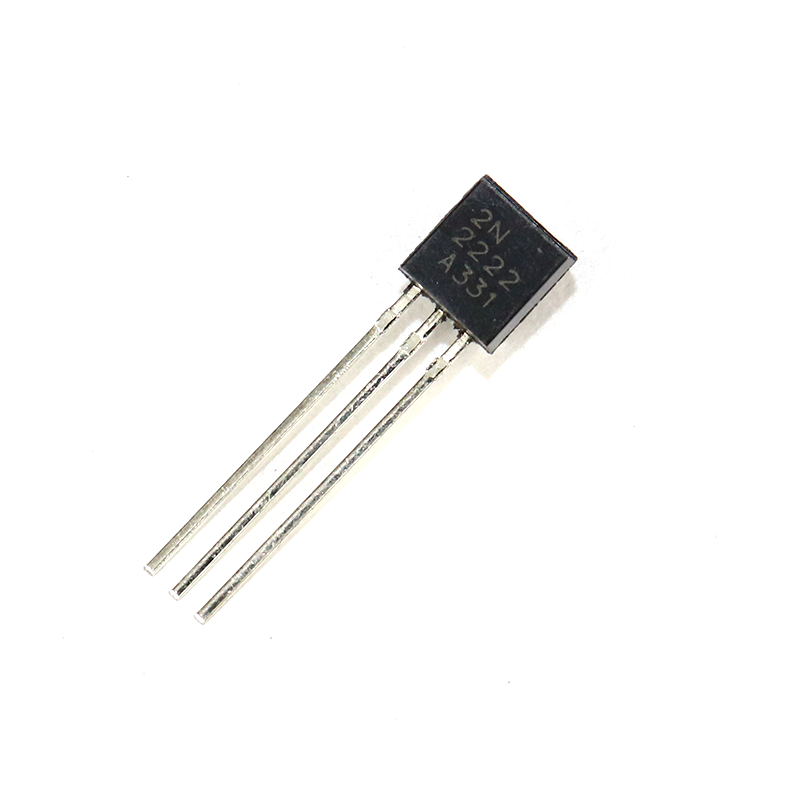
2N2222 NPN Transistor (Pack of 20)
Use a 2N2222 NPN transistor as a simple gate driver to control a P-Channel MOSFET from a microcontroller — a classic and inexpensive interface circuit.
Common Mistakes and How to Avoid Them
Even experienced builders make these errors. Here is what to watch for:
1. Floating Gate
If the Gate is not connected to anything and you power the circuit, stray electric fields can partially turn the MOSFET on or cause erratic behaviour. Always include a pull-down resistor (10kΩ) from Gate to Source for N-Channel, or a pull-up resistor to V+ for P-Channel.
2. Insufficient Gate Voltage
Using a 3.3V Arduino to drive a non-logic-level MOSFET will leave it partially on. The RDS(on) could be 10x higher than rated, generating excessive heat. Choose logic-level parts or add a gate driver.
3. No Heat Sink on High-Current Devices
Even with low RDS(on), a MOSFET switching 10A will dissipate power (P = I² x RDS(on)). At 10A and 22mΩ, that is 2.2W — enough to need a heat sink on a TO-220 package.
4. Exceeding VGS(max)
The gate oxide is fragile. Most MOSFETs specify VGS(max) of ±20V. Exceeding this even momentarily destroys the device. If your drive voltage might spike, add a 15V Zener diode from Gate to Source as protection.
5. No Flyback Diode on Inductive Loads
Motors, relays, and solenoids generate a voltage spike when the MOSFET switches off — back-EMF. This spike can exceed the MOSFET drain-source breakdown voltage. Place a flyback diode (1N4007) across the load, cathode to V+, anode to Drain.

LCR-T4 Transistor Tester with LCD
Identify mystery MOSFETs, verify pinouts, and measure threshold voltage automatically — this handy tester supports MOSFETs, BJTs, JFETs, SCRs, and more.
Frequently Asked Questions
What is the difference between a MOSFET and a BJT transistor?
A BJT is current-controlled: you must supply base current proportional to the collector current you want. A MOSFET is voltage-controlled: you apply a voltage to the gate and draw almost no current, making it far more efficient in switching applications. MOSFETs also have lower on-state losses at high currents, which is why they dominate in power electronics and motor drivers.
Can I use a MOSFET directly with an Arduino (5V) output?
Yes, but only if you choose a logic-level MOSFET rated for 4.5V or lower gate drive. The IRLZ44N is a popular example. Standard power MOSFETs like the IRF540N need 10V at the gate to fully turn on and will overheat if driven directly from 5V logic. For 3.3V microcontrollers (ESP32, ESP8266), look for MOSFETs rated at 2.5V gate drive.
Why do N-Channel MOSFETs have lower on-resistance than P-Channel?
N-Channel MOSFETs use electrons as the charge carrier, and electrons have roughly 2-3 times higher mobility than holes (used in P-Channel devices). Higher carrier mobility means the channel can conduct more current with less resistance for the same die area, resulting in lower RDS(on) and better efficiency.
What does RDS(on) mean and why does it matter?
RDS(on) is the drain-to-source resistance when the MOSFET is fully on. It determines how much power the MOSFET dissipates as heat: P = I squared times RDS(on). A MOSFET with 10mΩ switching 10A dissipates only 1W, while one with 200mΩ dissipates 20W — requiring a much larger heat sink or causing failure.
When should I use a P-Channel MOSFET instead of N-Channel?
Use a P-Channel MOSFET when you need a simple high-side switch — where the load sits between the MOSFET and GND, and the MOSFET source connects to the positive supply. This avoids the need for a bootstrap or charge-pump gate driver required by N-Channel high-side configurations. P-Channel is common in battery protection circuits, USB power switches, and simple power-path control.
Start Experimenting with MOSFETs Today
Understanding MOSFET basics opens up a huge range of projects: motor speed controllers, electronic loads, synchronous buck converters, class-D amplifiers, and solid-state relays are all built around these versatile devices. The key takeaways: N-Channel is your go-to for low-side switching with lower losses, P-Channel simplifies high-side switching at the cost of slightly higher RDS(on), and always ensure your gate drive voltage is appropriate for the specific MOSFET you choose.
Pick up a few logic-level MOSFETs, a breadboard, and some jumper wires, and start experimenting. Once you have seen a MOSFET switch a 12V load cleanly from a 3.3V microcontroller signal, the concept clicks instantly.

Female to Female Breadboard Jumper Wires – 40Pcs
Essential for building MOSFET circuits on a breadboard — clean, reliable 40-piece jumper wire sets in 10cm length for quick prototyping.


Add comment