
Building a precise multi-channel weighing system using load cells and the HX711 24-bit ADC amplifier is one of the most rewarding embedded electronics projects you can take on. Whether you are designing an industrial sorting conveyor, a multi-bin ingredient dispenser, or a platform scale that requires four-corner averaging, understanding the advanced capabilities of the HX711 and how to daisy-chain multiple units opens up a world of possibilities. This comprehensive guide walks you through every layer — from the physics of strain-gauge load cells to the firmware architecture needed to read six or more channels simultaneously on a single Arduino.
1. How Load Cells Work: Strain Gauges and Wheatstone Bridges
A load cell is a transducer that converts mechanical force into an electrical signal. Inside every load cell are one or more strain gauges — thin metallic foil elements bonded to a flexible substrate. When the load cell body deforms under weight, the foil stretches or compresses, changing its electrical resistance. This resistance change is typically just a few milliohms, which is why signal conditioning is so critical.
Most single-point and bar-type load cells use a full Wheatstone bridge with four active gauges. The bridge excitation voltage (typically 5 V from the HX711’s E+ and E- pins) causes a differential output voltage (S+ and S-) proportional to the applied load. A 10 kg load cell rated at 2 mV/V produces a maximum differential output of 10 mV at 5 V excitation — well below the noise floor of a standard Arduino ADC, which is why you need the HX711’s 24-bit instrumentation amplifier.
Key parameters to match between your load cell and your application:
- Rated capacity: The maximum safe load (1 kg, 10 kg, 50 kg, etc.).
- Sensitivity: Typically 1–3 mV/V. Higher sensitivity = easier to amplify cleanly.
- Creep: Signal drift under constant load over time. Important for dispensing applications.
- IP rating: Matters for food, liquid, or outdoor use.
2. HX711 Deep Dive: Channels, Gain, and Timing
The HX711 is a purpose-built 24-bit analog-to-digital converter designed specifically for weigh-scale and industrial control applications. It integrates a low-noise programmable-gain amplifier (PGA), an internal voltage regulator, and an oscillator that clocks the ADC. Communication is not I2C or SPI — it uses a proprietary two-wire protocol over the DOUT (data) and PD_SCK (clock) pins.
Two input channels:
- Channel A: Selectable gain of 128 or 64. At 128, the full-scale differential input range is ±20 mV — perfect for standard 2 mV/V load cells at 5 V excitation.
- Channel B: Fixed gain of 32. Useful for secondary sensors with larger output ranges.
Data rate: The RATE pin sets either 10 SPS (RATE = 0, tied low) or 80 SPS (RATE = 1, tied high). For multi-channel polling, 80 SPS is preferable to reduce round-robin latency.
The conversion cycle: After a conversion completes, DOUT goes LOW. The host then clocks out 24 bits (MSB first) plus 1–3 extra pulses that simultaneously set the gain/channel for the NEXT conversion. This means channel selection is always one conversion behind — a gotcha that trips up many beginners.
Power-down mode: Holding PD_SCK high for >60 µs puts the HX711 in power-down mode. This is useful in battery systems but must be avoided in multi-chip topologies where the clock line is shared.
3. Multi-Channel Architectures: Options and Trade-offs
When you need more than one or two weighing channels, you have several architectural choices:
Option A: One HX711 per Load Cell (Independent Pins)
Each HX711 module gets its own DOUT and PD_SCK pins on the microcontroller. This is the simplest approach and allows fully independent polling, but consumes 2 GPIO pins per channel. An Arduino Uno supports up to 7 channels this way (14 digital I/O pins divided by 2).
Option B: Shared Clock, Independent DOUT
All HX711 modules share a single PD_SCK clock line; each has its own DOUT line. The host broadcasts clock pulses simultaneously to all chips. Since all chips were powered up together, they tend to complete conversions at similar times. This reduces GPIO usage to (N+1) pins for N channels and allows approximate simultaneous sampling.
Caveat: The gain/channel select bits at the end of each 24-clock burst affect all chips simultaneously. Since Channel A gain 128 requires 25 clocks and Channel A gain 64 requires 26 clocks, you must ensure all chips are configured identically when sharing a clock.
Option C: I2C GPIO Expander + Independent HX711s
Use an MCP23017 or PCF8574 to multiplex DOUT lines through I2C, keeping the MCU GPIO count low. This is ideal for ESP32 or Arduino Nano projects where GPIO is scarce but I2C bandwidth is available.
Option D: Dedicated Weigh-Scale IC (NAU7802, ADS1230)
For high-channel-count industrial designs, chips like the NAU7802 (true I2C address-selectable) or multiple ADS1232 (SPI) may be more appropriate. However, the HX711’s low cost and wide ecosystem make it unbeatable for maker and prototyping use.
4. Wiring Multiple HX711 Modules to Arduino
Below is the wiring for a 4-channel system using shared clock (Option B). All HX711 modules share VCC (5 V), GND, and PD_SCK. Each has an individual DOUT line.
HX711 #1:  VCC→5V, GND→GND, PD_SCK→D2, DOUT→D3
HX711 #2:  VCC→5V, GND→GND, PD_SCK→D2, DOUT→D4
HX711 #3:  VCC→5V, GND→GND, PD_SCK→D2, DOUT→D5
HX711 #4:  VCC→5V, GND→GND, PD_SCK→D2, DOUT→D6

Load Cell wiring (each cell to its HX711):
  Red   → E+ (excitation positive)
  Black → E- (excitation negative)
  White → A- (signal negative)
  Green → A+ (signal positive)
  Yellow (shield) → GND (if present)
Important notes:
- Keep load cell cable lengths equal between channels to minimise thermal EMF mismatches.
- Route load cell cables away from power lines and motor drivers. Use shielded cable where possible.
- Decouple each HX711’s VCC with a 100 nF ceramic capacitor placed as close as possible to the VCC pin.
- If your load cells have a yellow (drain/shield) wire, connect it to GND at the HX711 end only — avoid ground loops.
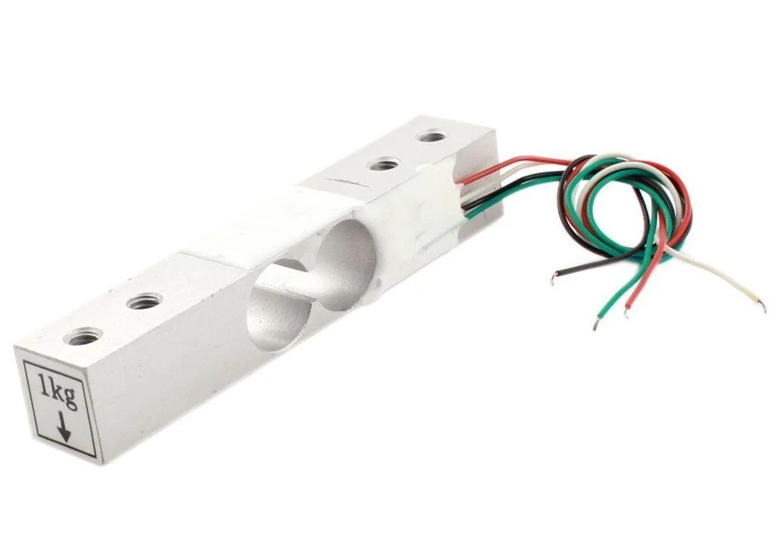
1Kg Load Cell – Electronic Weighing Scale Sensor
Ideal starter load cell for multi-channel dispensing systems. Full Wheatstone bridge, 2 mV/V sensitivity, compatible with HX711 at both 5 V and 3.3 V excitation.
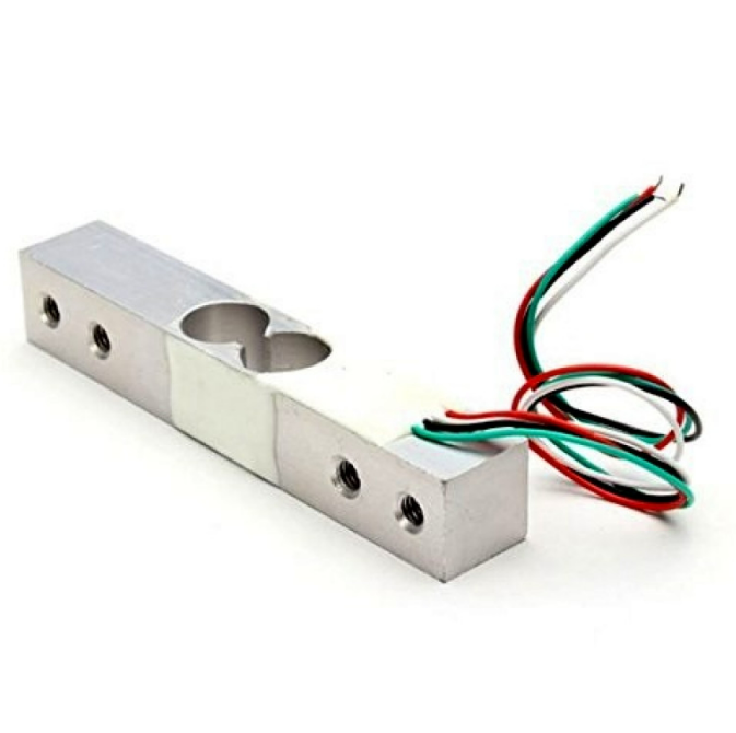
10Kg Load Cell – Electronic Weighing Scale Sensor
Heavy-duty bar-type load cell suitable for platform scales and industrial multi-channel weigh systems. Pairs perfectly with HX711 at gain 128.
5. Arduino Library Setup and Channel Polling
The most widely used library is bogde/HX711, available through the Arduino Library Manager. Install it, then use the following sketch structure for 4-channel shared-clock polling:
#include <HX711.h>

#define NUM_CHANNELS 4
const int DOUT_PINS[NUM_CHANNELS] = {3, 4, 5, 6};
const int CLK_PIN = 2;

HX711 scales[NUM_CHANNELS];
float calibrationFactors[NUM_CHANNELS] = {420.0, 418.5, 421.2, 419.8};

void setup() {
  Serial.begin(115200);
  for (int i = 0; i < NUM_CHANNELS; i++) {
    scales[i].begin(DOUT_PINS[i], CLK_PIN);
    scales[i].set_scale(calibrationFactors[i]);
    scales[i].tare(); // Zero at startup
  }
  Serial.println("All channels tared. Ready.");
}

void loop() {
  for (int i = 0; i < NUM_CHANNELS; i++) {
    if (scales[i].is_ready()) {
      float weight = scales[i].get_units(5); // 5-sample average
      Serial.print("CH"); Serial.print(i + 1);
      Serial.print(": "); Serial.print(weight, 2);
      Serial.println(" g");
    }
  }
  delay(100);
}
The get_units(5) call takes 5 readings and returns their average, significantly reducing noise without a separate filter implementation. The calibration factor converts raw ADC counts to grams.
6. Calibration: Two-Point and Span Correction
Calibration is the single most important step for accurate weighing. The HX711 two-point calibration procedure:
- Zero (tare): With no load on the cell, call
scale.tare(). This records the current raw ADC reading as the zero offset. - Span: Place a known reference weight (as close to mid-scale as practical). Read the raw value with
scale.get_value(10)(10-sample average). Divide the raw count by the known weight in your desired units. This quotient is your calibration factor.
// Calibration sketch
scale.tare();
Serial.println("Place 500g reference weight, press any key");
while (!Serial.available());
float factor = scale.get_value(20) / 500.0; // grams
Serial.print("Calibration factor: ");
Serial.println(factor);
Pro tip: Store calibration factors in EEPROM so they survive power cycles:
#include <EEPROM.h>
// Store float at address 0 + (channel * 4)
void saveCalFactor(int ch, float factor) {
  EEPROM.put(ch * 4, factor);
}
float loadCalFactor(int ch) {
  float f; EEPROM.get(ch * 4, f); return f;
}
For highest accuracy, perform the two-point calibration at operating temperature, as load cell sensitivity has a small temperature coefficient (typically 0.02%/°C for quality cells). Recalibrate if ambient temperature changes by more than 10 °C.
7. Averaging, Filtering, and Noise Reduction
Even with 24-bit resolution, HX711 readings contain noise from vibration, EMI, and thermal drift. These techniques help:
Moving Average
Maintain a circular buffer of the last N readings. A window of 8–16 samples (at 80 SPS = 100–200 ms latency) dramatically smooths out impulse noise from vibration:
#define WIN 16
long buf[WIN]; int idx = 0;
long movingAvg(long newVal) {
  buf[idx++ % WIN] = newVal;
  long sum = 0;
  for (int i = 0; i < WIN; i++) sum += buf[i];
  return sum / WIN;
}
Median Filter
For environments with sharp vibration spikes (conveyor belts, machinery), a median filter over 5–7 samples rejects outliers better than averaging. Collect N samples, sort them, return the middle value.
Exponential Moving Average (EMA)
EMA is computationally cheap and excellent for slow-changing loads:
ema = alpha * newReading + (1 - alpha) * ema;
Use alpha = 0.1–0.3 depending on desired responsiveness.
Hardware Noise Reduction
- Mount load cells on vibration-isolated platforms (rubber feet, anti-vibration pads).
- Use a common-mode choke on load cell cables near the HX711 input.
- Add 10 nF capacitors from each signal wire (A+, A-) to GND at the HX711 input pins.
- Set RATE = 0 (10 SPS) when ultra-low noise is more important than speed.
8. Project: 4-Corner Platform Scale
A platform scale uses four load cells — one under each corner of the platform — and sums all four readings to get the total weight. This compensates for off-centre loading, which would otherwise skew the reading if using a single centre load cell.
Mechanical design: Each load cell sits in a mounting bracket that allows the top surface to deflect slightly under load while keeping the cell body fixed. A 3 mm aluminium plate makes a good platform for loads up to 20 kg when using four 5 kg load cells.
Firmware for summed weighing:
float totalWeight() {
  float sum = 0;
  for (int i = 0; i < 4; i++) {
    sum += scales[i].get_units(3);
  }
  return sum; // Total load in grams
}

// Optional: detect off-centre loading
void printCornerLoads() {
  float corners[4];
  float total = 0;
  for (int i = 0; i < 4; i++) {
    corners[i] = scales[i].get_units(3);
    total += corners[i];
  }
  Serial.print("Total: "); Serial.println(total, 1);
  for (int i = 0; i < 4; i++) {
    Serial.print("Corner "); Serial.print(i+1);
    Serial.print(": "); Serial.print(corners[i] / total * 100, 1);
    Serial.println("%");
  }
}
This corner load analysis is invaluable for diagnosing mechanical issues — if one corner consistently reads 40% of the total while the others read ~20%, that corner’s mounting is too stiff or the platform is not level.
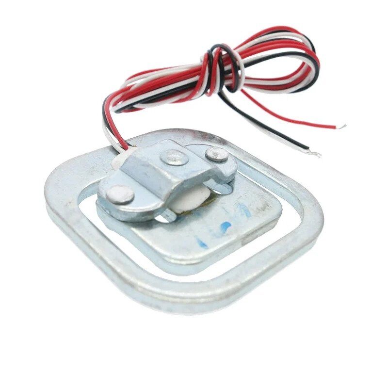
50kg Half-Bridge Load Cell Sensor
High-capacity load cell for body or industrial platform scales. Use two in a half-bridge configuration or four for full platform-scale accuracy.
9. Project: 6-Channel Ingredient Dispenser
A 6-channel dispenser independently measures the weight of six ingredient bins and controls an auger or valve motor on each bin to dispense precise amounts. This is a common automation need in food processing, animal feed, and laboratory environments.
System overview:
- 6 × 1 kg load cells, each on a separate HX711 (shared clock, GPIO D2; DOUT D3–D8)
- 6 × relay modules to control 12 V DC motors
- Arduino Mega 2560 (ample GPIO)
- 16×2 LCD display showing current dispense progress
Dispense control loop:
struct Channel {
  float target;    // grams to dispense
  float baseline;  // weight before dispense
  bool  active;
  int   relayPin;
};

void startDispense(Channel &ch, float grams) {
  ch.baseline = scales[&ch - channels].get_units(5);
  ch.target   = grams;
  ch.active   = true;
  digitalWrite(ch.relayPin, HIGH); // Motor ON
}

void updateDispense(int idx) {
  Channel &ch = channels[idx];
  if (!ch.active) return;
  float dispensed = scales[idx].get_units(3) - ch.baseline;
  if (dispensed >= ch.target * 0.95) { // 5% overshoot guard
    digitalWrite(ch.relayPin, LOW);   // Motor OFF
    ch.active = false;
  }
}
The 5% early shutoff compensates for motor coasting — material in the auger or valve continues flowing for a fraction of a second after the motor stops. Tune this percentage for your specific motor/material combination.
10. Troubleshooting Common Issues
| Symptom | Likely Cause | Fix |
|---|---|---|
| All channels read 0 | CLK line floating HIGH (power-down triggered) | Add 10 kΩ pull-down on PD_SCK |
| Random channel reads max value | DOUT lines cross-coupled | Verify DOUT pin assignments in code |
| Weight drifts after tare | Thermal drift or creep | Allow 15-min warm-up; re-tare periodically |
| Scale reads negative | Load cell polarity reversed | Swap A+ and A- wires OR negate cal factor |
| is_ready() always returns false | RATE pin not connected (defaults 10 SPS) or power issue | Check VCC; tie RATE to GND for 10 SPS |
FAQ
Can I use more than 4 HX711 modules on an Arduino Uno?
Yes. With shared-clock wiring you only need N+1 GPIO pins — one clock plus one DOUT per module. An Arduino Uno has 14 digital I/O pins, so you can run up to 13 HX711 modules (though the polling loop will become slow at 10 SPS). Use an Arduino Mega for 6+ channels for comfortable pin headroom.
How accurate is a multi-channel HX711 system?
With proper calibration and a quality load cell, accuracy of 0.1–0.5% full scale is achievable. The HX711’s 24-bit ADC provides about 16 million counts of resolution, but practical noise limits you to roughly 16-bit effective resolution (about 65,000 counts) under typical lab conditions.
Can I use different capacity load cells on each channel?
Absolutely. Each HX711 is calibrated independently, so a 1 kg cell on CH1 and a 10 kg cell on CH2 will work fine. Just ensure the gain setting is appropriate — use gain 128 for small-range cells to maximise resolution.
What is the maximum cable length for load cells?
With shielded cable, runs up to 50 m are practical. For very long runs, consider a 4-wire remote sense connection and a higher-grade instrumentation amplifier like the INA128. The HX711 is designed for board-mounted use, but works well in controlled EMI environments up to 10–15 m with unshielded cable.
How do I prevent tare drift over long operating periods?
Implement an auto-tare that triggers when the scale has been unloaded (reading below a threshold) for more than N seconds. Store the tare offset in EEPROM and refresh it on every clean unload event. This compensates for slow creep over hours of operation.
Ready to Build Your Weighing System?
Pick up load cells, HX711 modules, and all the supporting components you need from Zbotic’s Sensors & Measurement collection. Fast delivery across India, with technical support from our engineering team.


Add comment