
Table of Contents
- What Is an LDR (Light Dependent Resistor)?
- How Does an LDR Work?
- Components Needed
- Circuit Diagram and Wiring
- Arduino Code for Automatic Night Lamp
- Calibrating the LDR Threshold
- Advanced LDR Projects
- Troubleshooting Common Issues
- Recommended Sensors from Zbotic
- Frequently Asked Questions
An automatic night lamp is one of the most satisfying beginner electronics projects — it solves a real-world problem (forgetting to switch lights on/off) with just a handful of cheap components. At the heart of it is a humble component called the LDR (Light Dependent Resistor), also known as a photoresistor. Paired with an Arduino, this sensor lets you build a lamp that knows exactly when it’s dark and when it’s bright, toggling a light source accordingly — no manual switches required.
In this comprehensive guide you will learn exactly how an LDR works, how to wire it with an Arduino, how to write the firmware, how to calibrate it for your environment, and how to extend the project into something more sophisticated. By the end you’ll have a fully functioning automatic night lamp and the knowledge to adapt it to dozens of other light-sensing applications.
What Is an LDR (Light Dependent Resistor)?
An LDR — Light Dependent Resistor — is a passive electronic component whose electrical resistance changes in response to the intensity of light falling on it. Unlike a fixed resistor that always has the same resistance, an LDR is essentially a variable resistor controlled by photons. It belongs to the broad family of photoconductive devices.
LDRs are made from semiconductor materials such as cadmium sulphide (CdS) or lead sulphide (PbS). The most common LDRs you’ll find in hobbyist kits use cadmium sulphide, which responds best to visible light in the 400–700 nm wavelength range — essentially the same spectrum the human eye perceives.
Key characteristics of a typical CdS LDR:
- Dark resistance: 1 MΩ to 10 MΩ (very high resistance with no light)
- Bright light resistance: 50 Ω to 1 kΩ (very low resistance in strong light)
- Response time: 20–200 ms depending on the type
- Operating voltage: Typically 5 V to 150 V; at 5 V (Arduino level) they work perfectly
- Power dissipation: Usually under 100 mW
The dramatic change in resistance — often three to four orders of magnitude — is what makes LDRs so useful. That resistance change can be converted into a voltage using a simple voltage divider, and that voltage can be read by any microcontroller’s analogue input.
How Does an LDR Work?
When light (photons) strikes the semiconductor material of an LDR, it excites electrons from the valence band into the conduction band. These newly freed electrons are now available as charge carriers, which reduces the material’s electrical resistance. The brighter the light, the more electrons are excited, and the lower the resistance falls.
In the dark, very few photons are available to excite electrons, so most electrons remain in the valence band and the resistance stays very high. This is why your LDR might read 1 MΩ when covered by your hand and drop to just a few hundred ohms under a bright lamp.
Voltage Divider Principle
To read resistance changes with Arduino (which reads voltages, not resistances), we use a voltage divider circuit:
- Connect 5 V → LDR → Junction → Fixed Resistor (10 kΩ) → GND
- Read the voltage at the Junction with Arduino’s analogRead()
- In bright light: LDR resistance is low → Junction voltage is HIGH
- In darkness: LDR resistance is high → Junction voltage is LOW
This gives a clean analogue reading between 0 and 1023 (10-bit ADC on Uno) that maps perfectly to light intensity.
Components Needed
Here is everything you need for this project. All items are readily available in India and most can be ordered from Zbotic:
- 1× Arduino Uno (or Nano / Mega)
- 1× LDR (GL5528 or similar CdS photoresistor)
- 1× 10 kΩ resistor (for the voltage divider)
- 1× LED (any colour; white or warm-white for lamp effect)
- 1× 220 Ω resistor (current-limiting for LED)
- 1× 5 V relay module (if controlling a mains lamp) or use a transistor for a simple LED circuit
- 1× NPN transistor (BC547 or 2N2222) if using a transistor-switched LED array
- Jumper wires
- Breadboard or PCB
- USB cable + PC for programming

20A Range Current Sensor Module ACS712
Pair your night lamp project with the ACS712 to also monitor the power consumption of your switched load — a great addition to smart home builds.
Circuit Diagram and Wiring
Basic LDR Voltage Divider (Analogue Read)
Follow these wiring steps carefully:
- Place the LDR across the breadboard straddling the centre gap.
- Connect one leg of the LDR to 5 V on the Arduino.
- Connect the other leg of the LDR to a junction node — call it A0.
- From the junction node, connect a 10 kΩ resistor to GND.
- Run a wire from the junction node to Arduino pin A0.
- Connect the LED anode (+) through a 220 Ω resistor to Arduino pin D9 (PWM capable).
- Connect the LED cathode (–) to GND.
- Connect Arduino GND to the breadboard’s ground rail.
Note: If controlling a mains bulb, insert a 5 V relay module between D9 and the bulb. Never connect mains voltage directly to Arduino pins.
Pin Summary Table
| Arduino Pin | Connected To |
|---|---|
| 5V | LDR leg 1 |
| A0 | LDR leg 2 / 10kΩ top |
| GND | 10kΩ bottom / LED cathode |
| D9 | 220Ω → LED anode |
Arduino Code for Automatic Night Lamp
Version 1: Simple ON/OFF with Threshold
// LDR Automatic Night Lamp - Basic Version
// Zbotic.in Tutorial

const int ldrPin = A0;    // LDR voltage divider output
const int ledPin = 9;     // LED or relay control pin
const int threshold = 400; // Adjust based on calibration (0-1023)

void setup() {
  pinMode(ledPin, OUTPUT);
  Serial.begin(9600);
  Serial.println("LDR Night Lamp Ready");
}

void loop() {
  int ldrValue = analogRead(ldrPin);
  Serial.print("LDR Value: ");
  Serial.println(ldrValue);

  if (ldrValue < threshold) {
    // Dark — turn lamp ON
    digitalWrite(ledPin, HIGH);
  } else {
    // Bright — turn lamp OFF
    digitalWrite(ledPin, LOW);
  }

  delay(200); // Small debounce delay
}
Version 2: Smooth Dimming with PWM (No Flickering)
Instead of a hard ON/OFF, this version gradually dims the LED as ambient light increases — much more elegant and prevents annoying flickering near the threshold:
// LDR Automatic Night Lamp - Smooth Dimming Version
// Zbotic.in Tutorial

const int ldrPin = A0;
const int ledPin = 9;  // Must be PWM pin

void setup() {
  pinMode(ledPin, OUTPUT);
  Serial.begin(9600);
}

void loop() {
  int ldrValue = analogRead(ldrPin); // 0 (dark) to 1023 (bright)

  // Map inversely: dark = full brightness, bright = off
  // Clamp between 100 and 700 for typical indoor conditions
  int clamped = constrain(ldrValue, 100, 700);
  int brightness = map(clamped, 100, 700, 255, 0);

  analogWrite(ledPin, brightness);

  Serial.print("LDR: "); Serial.print(ldrValue);
  Serial.print(" | Brightness: "); Serial.println(brightness);

  delay(100);
}
Version 3: Hysteresis to Prevent Rapid Toggling
// LDR Night Lamp with Hysteresis
// Prevents rapid ON/OFF flickering near threshold

const int ldrPin = A0;
const int ledPin = 9;
const int onThreshold  = 350; // Turn ON when value drops below this
const int offThreshold = 500; // Turn OFF when value rises above this

bool lampOn = false;

void setup() {
  pinMode(ledPin, OUTPUT);
  Serial.begin(9600);
}

void loop() {
  int ldrValue = analogRead(ldrPin);

  if (!lampOn && ldrValue < onThreshold) {
    lampOn = true;
    digitalWrite(ledPin, HIGH);
    Serial.println("Lamp ON (dark detected)");
  } else if (lampOn && ldrValue > offThreshold) {
    lampOn = false;
    digitalWrite(ledPin, LOW);
    Serial.println("Lamp OFF (bright detected)");
  }

  delay(250);
}
Calibrating the LDR Threshold
The exact threshold value you need depends on:
- The specific LDR’s characteristics (resistance curve)
- The value of your pull-down resistor (we used 10 kΩ; higher values shift the midpoint)
- Your environment (indoor artificial light vs outdoor sunlight vs night)
Calibration Procedure
- Upload Version 1 code and open the Serial Monitor at 9600 baud.
- Note the reading in full daylight — say it reads 850.
- Note the reading in your target darkness level (e.g., evening room with lights off) — say it reads 250.
- Set your
thresholdto the midpoint: (850 + 250) / 2 = 550. - For Version 3 hysteresis: set
onThreshold = 400andoffThreshold = 650(roughly ±150 around the midpoint).
A 10 kΩ pull-down gives good sensitivity for most indoor LDRs. If you find the readings are bunched too close together, try a 47 kΩ pull-down resistor to spread the range.
Advanced LDR Projects
1. LDR + RTC Combo (Time + Light)
Combine an LDR with an RTC module (DS3231) to only activate the lamp between certain hours AND when dark — perfect for security lighting that respects time zones.
2. LDR-Based Street Light Controller
Scale up by driving a relay that controls a 230 V AC street lamp or garden light. Use optocoupler isolation between the Arduino and the relay coil for safety.
3. LDR + IoT (ESP8266 / ESP32)
Replace Arduino Uno with an ESP8266 NodeMCU. Publish LDR readings to MQTT broker or ThingSpeak. Control the lamp remotely via app even when the LDR logic says otherwise.
4. Automatic Window Blinds
Use two LDRs (one facing east, one west) with a servo motor to automatically tilt window blinds based on sunlight direction.
5. Camera Auto-Exposure Reference
Log LDR values every minute to an SD card and use the data to characterise daily light patterns in your home — useful for photography or plant-growth experiments.
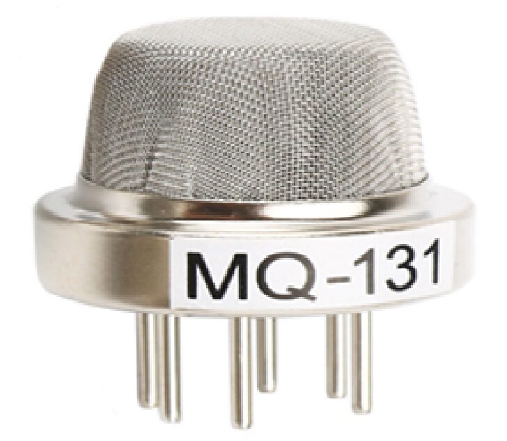
MQ-131 Ozone Gas Detection Sensor
Extend your smart lighting project to also detect ozone or air quality — one Arduino can handle both the LDR lamp control and the MQ-131 air sensor simultaneously.
Troubleshooting Common Issues
| Problem | Likely Cause | Fix |
|---|---|---|
| LED always ON | Threshold too high or LDR in shadow | Read serial monitor, lower threshold |
| LED always OFF | Threshold too low or wiring error | Check A0 connection, raise threshold |
| Rapid flickering | No hysteresis, light near threshold | Use Version 3 code with hysteresis |
| ADC reads 0 always | LDR legs shorted to GND | Check breadboard orientation |
| ADC reads 1023 always | Missing pull-down resistor | Add 10 kΩ from junction to GND |
| Relay chattering | No debounce / hysteresis | Add 500 ms delay after state change |
Recommended Sensors from Zbotic
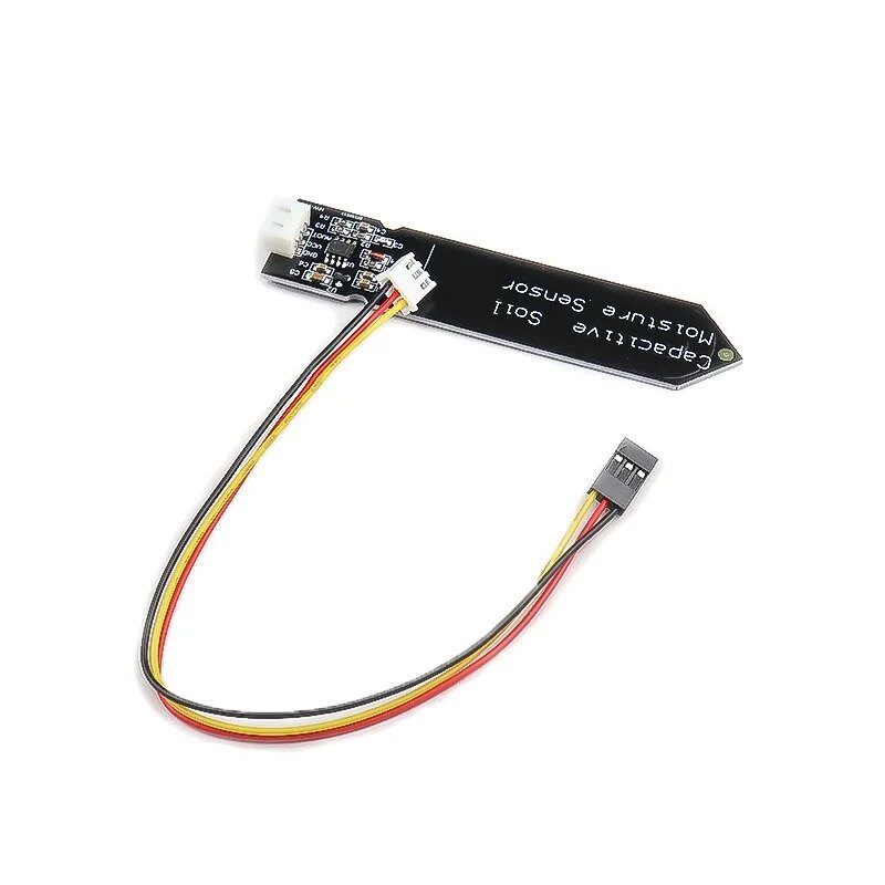
Capacitive Soil Moisture Sensor
Another analogue sensor that interfaces exactly like an LDR — once you master the voltage divider pattern, expand your project to also water plants automatically based on soil moisture.
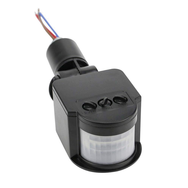
AC110-240V PIR Infrared Motion Sensor
Combine PIR motion detection with your LDR circuit for the ultimate smart lamp — lights only turn on when it’s dark AND someone is present in the room.
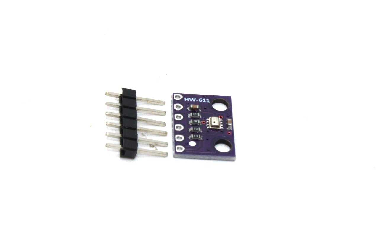
BMP280 Barometric Pressure Sensor
Add weather awareness to your smart lighting system — dim or brighten automatically based on atmospheric pressure changes that predict cloudy vs sunny conditions.
Frequently Asked Questions
Q1: Can I use an LDR module instead of a bare LDR?
Yes. LDR modules typically include the pull-down resistor and sometimes a comparator (LM393) that gives a digital HIGH/LOW output. They are easier to use but less flexible than reading the raw analogue value, which gives you finer control for dimming.
Q2: What is the ideal pull-down resistor value?
10 kΩ is the most common and works well for GL5528 LDRs in indoor environments. For very dim environments where the LDR barely changes, try 47 kΩ or 100 kΩ to increase the voltage swing across the readable range.
Q3: My lamp flickers when I move nearby. Why?
Your shadow is crossing the LDR threshold. Use the hysteresis Version 3 code and increase the gap between onThreshold and offThreshold. Alternatively, shield the LDR from direct lamp light to avoid feedback loops.
Q4: Can I control a 230 V AC bulb safely?
Yes, but always use a relay module with proper isolation and never touch the mains wiring while the circuit is powered. Use a quality relay rated for your load (e.g., 10 A 250 V AC) and house the high-voltage section in a separate insulated enclosure.
Q5: Will the LDR work outdoors?
Yes. Outdoor LDRs see a much wider light range. You may need to add a small enclosure or diffuser to prevent direct sunlight from saturating the sensor, and waterproof the circuit with conformal coating or a weatherproof box.
Q6: What is the difference between LDR and phototransistor?
An LDR changes resistance in response to light (slow, ~20-200 ms). A phototransistor switches current in response to light (fast, microseconds). LDRs are simpler and cheaper; phototransistors are better for high-speed light detection tasks like optical encoders or IR receivers.
Q7: Can I use this project with a Raspberry Pi?
Raspberry Pi lacks a built-in ADC, so you cannot read the LDR directly. You would need an external ADC (e.g., MCP3008) or use an Arduino as a co-processor. Alternatively, use the digital output of an LDR module (with onboard comparator).
Ready to Build Your Automatic Night Lamp?
The LDR + Arduino automatic night lamp is the perfect gateway into sensor-based electronics. You’ve now got three firmware versions, a calibration method, and a roadmap for advanced projects. Browse Zbotic’s full range of sensors and modules to pick up everything you need and start building today.


Add comment