
LTC4054 Solar Charger IC: Single Cell LiPo Charge Circuit
If you are building a solar-powered IoT device, a field sensor, or any portable electronics project, the LTC4054 solar charger IC single cell LiPo circuit is one of the most reliable and beginner-friendly solutions available. This tiny IC from Analog Devices handles all the complexity of lithium polymer battery charging — constant current, constant voltage, thermal regulation — in a small SOT-23-5 package that fits even the tightest PCB layouts. In this guide, we will walk through everything you need to understand about the LTC4054, from its internal architecture to a working solar-input charge circuit that Indian makers can build for under ₹500.
What Is the LTC4054 Charger IC?
The LTC4054 (also sold as the LT4054 or CN3058 clone in many Indian hobby stores) is a complete constant-current/constant-voltage linear charger for single-cell lithium-ion and lithium polymer batteries. Developed by Linear Technology (now part of Analog Devices), it is designed to operate directly from a USB port or any 4.25V to 6.5V DC source — including the output of a small solar panel with a filter capacitor.
What makes the LTC4054 particularly attractive for solar applications is its input voltage range. A standard 5V, 1W solar panel in Indian sunlight conditions typically outputs 5.5–6.0V at open circuit and drops to around 4.8–5.2V under load. This falls squarely within the LTC4054’s input range, making it possible to charge a 3.7V LiPo cell directly from a solar panel without any buck or boost converter in between.
The IC uses a simple resistor on the PROG pin to set the charge current — from as low as 100mA to a maximum of 1000mA. For solar applications where panel current is limited, you will typically set this between 150mA and 500mA depending on your panel’s watt rating.
Key Features and Specifications
- Input Voltage Range: 4.25V to 6.5V (ideal for 5V solar panels)
- Charge Voltage: 4.2V ± 1% (factory trimmed, no external trimming needed)
- Programmable Charge Current: Up to 1000mA via single resistor on PROG pin
- Charge Current Formula: IPROG = 1000V / RPROG (in kΩ, current in mA)
- Automatic Recharge: Restarts when battery drops below ~4.05V
- Charge Status Pin (/CHRG): Open-drain output drives an LED to indicate charging status
- Thermal Regulation: Automatically reduces current when junction temperature exceeds 115°C
- Package: SOT-23-5 (5-pin, very small)
- Quiescent Current: 250µA during charging, 2µA in shutdown
- No External Sense Resistor Needed
The thermal regulation feature is particularly important for solar applications. When the sun is intense and ambient temperatures are high (which is common across India in summer), the IC will automatically throttle back the charge current to prevent overheating — protecting both the IC and your LiPo cell from thermal damage.
Designing the Solar Charger Circuit
A complete LTC4054 solar charger circuit requires very few external components. Here is the minimal bill of materials and the circuit topology:
Minimal Circuit Components
- LTC4054 / CN3058 IC (SOT-23-5)
- 4.7µF ceramic capacitor on VIN pin (input bypass)
- 4.7µF ceramic capacitor on VBAT pin (output bypass)
- RPROG resistor to set charge current (see formula below)
- 1kΩ resistor + LED for charge status indicator
- 5V solar panel (1W or 2W recommended)
- Schottky diode (1N5817 or SS14) — optional but recommended to prevent battery backfeed to panel at night
Charge Current Resistor Calculation
Use this formula to find RPROG:
RPROG (kΩ) = 1000 / ICHG (mA)

Examples:
  300mA charge → RPROG = 1000/300 = 3.3 kΩ
  500mA charge → RPROG = 1000/500 = 2 kΩ
  200mA charge → RPROG = 1000/200 = 5 kΩ (use 4.7kΩ standard)
For a 1W solar panel, limit the charge current to 200mA maximum (1W ÷ 5V = 200mA). This matches well with a 4.7kΩ RPROG resistor. For a 2W panel, you can use 3.3kΩ for ~300mA. Always stay within 80% of the panel’s rated current to leave headroom for cloudy conditions.
Circuit Schematic Description
Connect the solar panel positive output through a Schottky diode (anode to panel, cathode to VIN). Place a 4.7µF capacitor from VIN to GND as close as possible to the IC. Connect RPROG through the chosen resistor to GND. Connect /CHRG through a 1kΩ resistor to an LED (cathode to GND, anode to resistor). Connect VBAT to the positive terminal of your LiPo cell with a 4.7µF bypass capacitor. GND connects to the negative of both the solar panel and LiPo.
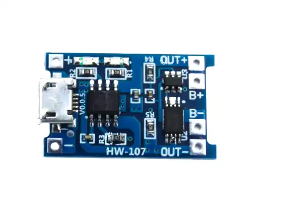
TP4056 1A Li-Ion Battery Charging Board Micro USB with Current Protection
A ready-made single cell LiPo charger module using the TP4056 IC — very similar in function to the LTC4054 but in a convenient breakout board with USB input and built-in protection. Great for prototyping before moving to a custom PCB.
Component Selection Guide
Solar Panel Selection
Choose a solar panel rated for 5V or 6V output. In India, small 5V/1W and 5V/2W epoxy solar panels are widely available at electronics markets and online. Avoid cheap 3.7V panels — they will barely charge the battery even in peak sunlight. A 6V/1W panel gives better charging headroom and is commonly used in solar garden lights.
Panel comparison for Indian makers:
- 5V/0.5W panel → Use 6.8kΩ RPROG for ~147mA (safe match)
- 5V/1W panel → Use 4.7kΩ RPROG for ~213mA (good match)
- 6V/2W panel → Use 3.3kΩ RPROG for ~303mA (good with a Schottky on input)
Why a Schottky Diode Matters
Without a Schottky diode between the solar panel and VIN, the LiPo battery can backfeed current through the panel’s internal diodes at night. This wastes energy and can discharge your battery. A 1N5817 (0.2–0.3V forward drop) is the standard choice. Avoid regular silicon diodes (1N4007) — their 0.7V drop wastes too much voltage from a 5V panel.
Capacitor Choice
Use X5R or X7R ceramic capacitors for both the input and output bypass. Avoid Y5V dielectrics — they lose capacitance significantly with DC bias. A 4.7µF/10V rated ceramic is ideal on the input side. On the battery side, 4.7µF/6.3V is sufficient since the battery voltage never exceeds 4.2V.

1S 12A 3.6V BMS Battery Protection Board for Li-ion Cell
Add this BMS board on the output side of your solar charger to protect the LiPo cell from over-discharge, short circuits, and over-current on the load side. Essential for any unattended solar deployment.
Building and Testing the Circuit
Step 1 — Breadboard Prototype
Because the LTC4054 is only available in SOT-23-5, you need a small SOT-23 breakout board for breadboard testing. These are available from local electronics suppliers. Alternatively, the TP4056 module is pin-compatible in function and available in a DIP-friendly breakout — use it for initial testing before designing your final PCB.
Step 2 — Verify Input Voltage
Before connecting the solar panel, measure its open-circuit voltage with a multimeter in direct sunlight. Ensure it is between 4.5V and 6.5V. If the voltage is too high (above 6.5V), add a series Zener diode (6.2V Zener) to clamp the input — though this is rarely needed with standard 5V panels.
Step 3 — Charge Current Verification
Measure the voltage across RPROG with your multimeter. The LTC4054 regulates this to approximately 1.0V when charging at the programmed current. So if RPROG = 4.7kΩ, the current should be 1.0V / 4700Ω ≈ 213mA. Verify this matches your expectation.
Step 4 — Battery Monitoring
Use a LiPo voltage tester to monitor the battery voltage as it charges. A fully depleted LiPo at 3.0V should reach 4.2V within a few hours depending on the charge current and capacity. The /CHRG LED should turn off (high-Z output) when the charge is complete.

1-8S Lipo Battery Voltage Tester without Alarm
Quickly check individual cell voltages and total pack voltage during testing. Works with 1S to 8S LiPo/LiFe/Li-ion packs. An essential bench tool when commissioning any battery charging circuit.
Common Mistakes and How to Avoid Them
Mistake 1 — Using Too Small a Bypass Capacitor
Many builders skip or undersize the input bypass capacitor. Without at least 4.7µF on VIN, the IC can oscillate when the solar panel’s series resistance causes voltage dips at the charge current frequency. Always place the bypass capacitor as close to the VIN pin as possible with short trace lengths.
Mistake 2 — Overrating Charge Current Relative to Panel
If you set RPROG for 500mA but your panel can only deliver 200mA, the panel voltage will collapse below the minimum input threshold (4.25V) and the charger will repeatedly enter and exit the UVLO (undervoltage lockout) state, causing the LED to blink erratically. Always size charge current to 80% or less of the panel’s short-circuit current.
Mistake 3 — No Night-Time Protection
Solar panels are essentially diodes. At night or in shade, a panel’s internal bypass diodes can allow the battery to discharge back into the panel circuitry. Always include the series Schottky diode on the VIN line.
Mistake 4 — Connecting Load Directly to VBAT Without BMS
The LTC4054 only protects against overcharge. It does not protect against over-discharge. If your load runs the battery below 2.5V, LiPo cells can be permanently damaged. Always add a 1S BMS board between the battery and your load circuit.
Mistake 5 — Ignoring Thermal Layout
In a high ambient temperature environment (which is common across India during May–June), the LTC4054’s thermal regulation will kick in and reduce charge current. While this is a protection feature, it means slower charging on hot days. Improve thermal dissipation by adding copper pours around the IC on your PCB.
Real-World Applications for Indian Projects
Weather Station Node
An ESP8266/ESP32 running in deep sleep mode with a BME280 sensor can run for months on a single 2000mAh LiPo. Add a 5V/1W solar panel with the LTC4054 circuit, and you have a perpetually self-charging weather station for a rooftop or farm field. Power consumption in deep sleep is around 20µA, with brief 150mA spikes during WiFi transmission every 15 minutes.
Agricultural Soil Sensor
Capacitive soil moisture sensors combined with an Arduino Nano or ATtiny85 can be solar powered with this circuit. Ideal for Indian farms where power infrastructure is unreliable but sunlight is abundant. Mount the panel on a stake above the canopy for maximum charging even in partial shade.
GPS Asset Tracker
A SIM800L GSM module with a neo-6M GPS and ATmega328 can be built into a waterproof enclosure with a small LiPo and solar panel. The LTC4054 circuit keeps it charged during the day even when parked outdoors. This is useful for tracking vehicles, construction equipment, or livestock in rural areas.
Solar Garden Light Controller
Replace the generic controller in a solar garden light kit with a custom LTC4054 circuit. Add a comparator circuit that turns on an LED driver at dusk (when VIN drops below 3V) and switches it off at dawn. You get a clean, efficient, custom-designed solar light.
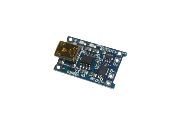
TP4056 1A Li-ion Lithium Battery Charging Module With Current Protection – Mini USB
This compact TP4056 module works excellently as a drop-in solar charger when fed from a regulated 5V panel. Includes over-discharge protection built in. Ideal for quick solar project builds without PCB design.
Frequently Asked Questions
Can I use the LTC4054 with a 6V solar panel?
Yes, the LTC4054 accepts up to 6.5V on its VIN pin. A 6V rated panel typically outputs 6.5–7V open circuit, which could exceed the maximum. Always add a Schottky diode (0.3V drop) in series to bring the effective input to ~6.2–6.7V, keeping it within spec. Alternatively, use a Zener clamp on the input.
What is the difference between LTC4054 and CN3058?
The CN3058 is a Chinese clone that is functionally nearly identical to the LTC4054. It uses the same pin-out and resistor formula. The main differences are in tolerance — the CN3058’s charge voltage accuracy is ±2% vs ±1% for the LTC4054, and its thermal regulation threshold may differ slightly. For most hobby projects, the CN3058 works just fine and is easier to source in India.
How long will it take to charge a 1000mAh LiPo with a 1W panel?
A 1W panel provides roughly 200mA of charge current. Charging a 1000mAh cell from 20% (800mAh to replenish) at 200mA would take theoretically 4 hours. In practice, add 20–30% for charging inefficiency and solar intermittency, so expect 5–6 hours of good sunlight for a full charge.
Does the LTC4054 support MPPT (Maximum Power Point Tracking)?
No. The LTC4054 is a simple linear charger with no MPPT capability. For maximum solar panel efficiency, you need a dedicated MPPT controller like the CN3791. However, for small panels under 2W with a properly sized charge current, the efficiency loss is minimal and the simplicity of the LTC4054 makes it the preferred choice for most low-power IoT applications.
Can I charge two cells in parallel with the LTC4054?
The LTC4054 is designed for single-cell (1S) charging only — it targets a 4.2V charge voltage. You can connect two cells in parallel (effectively doubling capacity while keeping voltage at 3.7V nominal) and the charger will still work correctly, though charge time will double. Never connect cells in series — the voltage would exceed the IC’s output rating.
Build Your Solar LiPo Charger Today
The LTC4054 (or its TP4056/CN3058 equivalent) is one of the most cost-effective ways to add solar charging to any embedded project. Whether you are building a remote sensor for your farm, a wildlife camera, or a portable ham radio power supply, this circuit gives you reliable, maintenance-free power. Zbotic stocks all the battery modules, BMS boards, and charging components you need to complete your build — at competitive prices with fast shipping across India.


Add comment