
Understanding inverse kinematics for a robotic arm with Arduino is the gateway to building truly precise robotic manipulators. Forward kinematics tells you where the end-effector ends up given servo angles — inverse kinematics (IK) does the opposite: you specify a target position in 3D space and the algorithm calculates the exact joint angles needed to reach it. This guide covers the underlying trigonometry, 2-DOF and 3-DOF analytical solutions, and complete Arduino servo code you can run today.
What Is Inverse Kinematics?
A robotic arm is a chain of rigid links connected by joints (usually rotational servos). The end-effector is the tip — a gripper, pen, or tool. Inverse kinematics answers the question: “Which servo angles do I need to put the end-effector at position (x, y, z)?”
This is fundamentally harder than forward kinematics because:
- Multiple solutions often exist (the arm can reach a point from elbow-up or elbow-down configurations).
- Some target positions lie outside the workspace — you must detect and reject these.
- Joint limits must be respected — real servos only rotate 180° or 270°.
For hobby robotic arms with 2–6 DOF, analytical (closed-form) IK using trigonometry is fast enough for Arduino’s 16 MHz AVR processor. Neural network or numerical IK is unnecessary for this scale.
Forward vs Inverse Kinematics
Forward kinematics (FK) uses given angles → compute position. For a 2-DOF planar arm with link lengths L1 and L2:
x = L1*cos(θ1) + L2*cos(θ1 + θ2)
y = L1*sin(θ1) + L2*sin(θ1 + θ2)
Inverse kinematics reverses this: given (x, y) → compute (θ1, θ2). This requires solving simultaneous transcendental equations, which is where trigonometric identities come in.
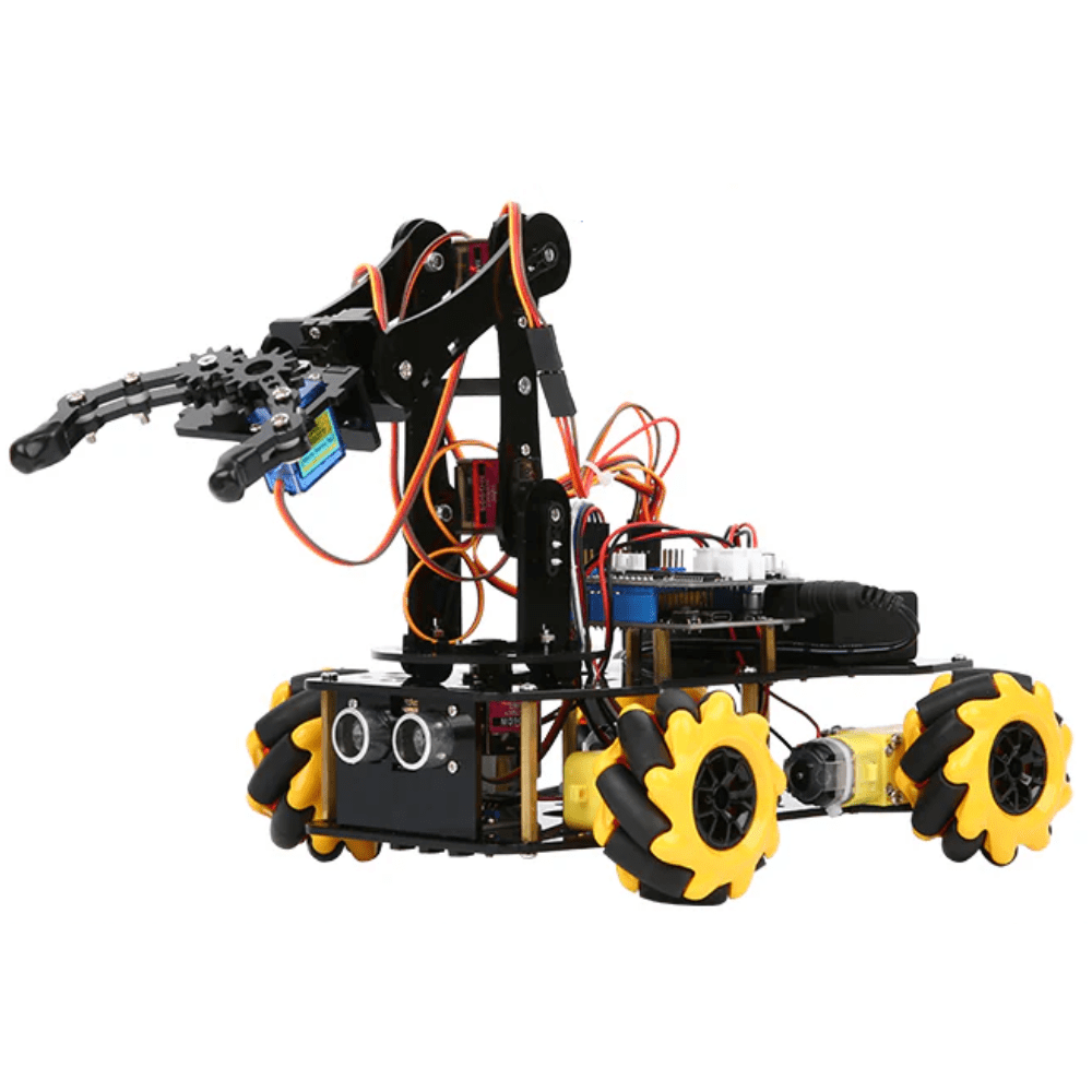
ACEBOTT ESP32 5-DOF Robot Arm Kit Expansion Pack (QD001–QD007)
A complete 5-DOF robotic arm kit with ESP32 control board, metal servo brackets, and structured cabling — ideal for implementing and testing IK algorithms.
2-DOF Planar Arm: The Math
Given target coordinates (x, y) and link lengths L1, L2:
Step 1 — compute the cosine of θ2 using the law of cosines:
cos(θ2) = (x² + y² - L1² - L2²) / (2 × L1 × L2)If |cos(θ2)| > 1, the target is out of reach — handle this gracefully.
Step 2 — compute θ2:
θ2 = ±arccos(cos(θ2))
# + gives elbow-up, − gives elbow-down solution
Step 3 — compute θ1:
k1 = L1 + L2×cos(θ2)
k2 = L2×sin(θ2)
θ1 = atan2(y, x) − atan2(k2, k1)
Using atan2(y, x) instead of plain atan is critical — it handles all four quadrants correctly and avoids division-by-zero errors at x = 0.
Extending to 3-DOF with a Wrist
A 3-DOF arm adds a base rotation joint (θ0 around the Z-axis). This transforms the 3D problem into a 2D planar IK problem:
- θ0 (base rotation):
θ0 = atan2(y_world, x_world) - Projected radius in the XY plane:
r = sqrt(x² + y²) - Now solve 2-DOF IK with coordinates (r, z_world) using the equations above.
For a 5-DOF or 6-DOF arm, you typically solve the first 3 joints with analytical IK to position the wrist centre, then solve the last 3 joints (wrist orientation) separately using Euler angles.
Arduino IK Code with Servo Control
Here is a complete Arduino sketch for a 3-DOF arm using the Servo library:
#include <Servo.h>
#include <math.h>

Servo base, shoulder, elbow;

const float L1 = 120.0; // upper arm length mm
const float L2 = 100.0; // forearm length mm

void setup() {
  Serial.begin(9600);
  base.attach(9);
  shoulder.attach(10);
  elbow.attach(11);
}

bool inverseKinematics(float x, float y, float z,
                       float &a0, float &a1, float &a2) {
  // Base angle
  a0 = degrees(atan2(y, x));

  // Project to 2D
  float r = sqrt(x*x + y*y);

  // 2-DOF IK in (r, z) plane
  float c2 = (r*r + z*z - L1*L1 - L2*L2) / (2*L1*L2);
  if (abs(c2) > 1.0) return false; // unreachable

  float s2 = sqrt(1.0 - c2*c2); // elbow-up
  a2 = degrees(atan2(s2, c2));   // elbow angle

  float k1 = L1 + L2*c2;
  float k2 = L2*s2;
  a1 = degrees(atan2(z, r) - atan2(k2, k1)); // shoulder angle

  // Clamp to servo physical limits
  a0 = constrain(a0, 0, 180);
  a1 = constrain(a1, 0, 180);
  a2 = constrain(a2, 0, 180);
  return true;
}

void moveTo(float x, float y, float z) {
  float a0, a1, a2;
  if (inverseKinematics(x, y, z, a0, a1, a2)) {
    base.write((int)a0);
    shoulder.write((int)a1);
    elbow.write((int)a2);
    Serial.print("Moved: ");
    Serial.print(a0); Serial.print(" ");
    Serial.print(a1); Serial.print(" ");
    Serial.println(a2);
  } else {
    Serial.println("Target out of reach!");
  }
}

void loop() {
  // Demo: trace a square
  moveTo(100, 0, 80);  delay(1000);
  moveTo(100, 50, 80); delay(1000);
  moveTo(80,  50, 50); delay(1000);
  moveTo(80,  0, 50);  delay(1000);
}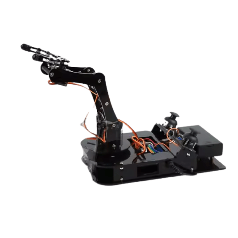
ACEBOTT ESP32 Programmable Robot Arm Kit for Beginners – QD022
A beginner-friendly ESP32 robot arm kit with guided coding exercises. Perfect for students learning IK concepts with real hardware and pre-built structural parts.
Hardware Setup: Arm Kit & Servos
For a hobby 3-DOF arm, you will need:
- 3× SG90 or MG90S servos — SG90 for light loads (pen plotting), MG90S metal gear for heavier grippers
- Servo brackets / horns — aluminium U-brackets give much better rigidity than 3D-printed parts
- Arduino Uno or Nano — sufficient for 3-DOF; use Arduino Mega for 6-DOF (more PWM pins)
- External 5V/3A power supply — never power multiple servos from the Arduino 5V pin
- Acrylic or aluminium arm base
For servo power, use a dedicated 5V buck converter or a 4× AA battery pack. Three SG90 servos can draw 1.5A stall current combined — far beyond the Arduino’s onboard regulator.

DIY Acrylic Robot Manipulator Mechanical Arm Kit
Laser-cut acrylic arm structure with all mounting hardware included. Bring your own servos and Arduino to build a full 4-DOF manipulator for IK experiments.
Workspace Limits & Singularities
The workspace of a 2-DOF planar arm is an annulus (ring) with:
- Maximum reach: L1 + L2 (fully extended)
- Minimum reach: |L1 − L2| (fully folded)
A singularity occurs when the arm is fully stretched or completely folded — at these configurations the Jacobian (rate of change of position w.r.t. angles) becomes degenerate and small target movements require infinite joint velocity. Always add a guard in your code:
float dist = sqrt(x*x + y*y + z*z);
if (dist > L1 + L2 - 5.0 || dist < abs(L1 - L2) + 5.0) {
  Serial.println("Near singularity — aborting");
  return false;
}
The 5 mm buffer prevents near-singular behaviour that causes servo jitter and mechanical stress.
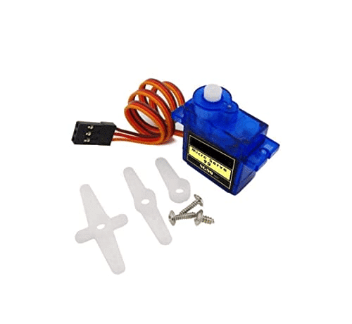
TowerPro SG90 180 Degree Rotation Servo Motor
The classic 9g micro servo used in thousands of robotic arm builds. Compact, affordable, and directly compatible with Arduino’s Servo library — no driver needed.
Frequently Asked Questions
What is the difference between analytical and numerical inverse kinematics?
Analytical IK derives closed-form trigonometric equations for exact solutions — fast and deterministic, suitable for Arduino. Numerical IK uses iterative methods (like Jacobian pseudo-inverse or gradient descent) to approximate solutions — slower but handles arbitrary DOF configurations.
Can I use inverse kinematics on Arduino Nano?
Yes. Analytical IK for 2-DOF and 3-DOF arms uses only basic trig (atan2, acos, sqrt) which the Arduino Nano’s AVR processor handles in under 1ms. Include <math.h> and use float arithmetic. Avoid double precision — it’s no faster on AVR and wastes RAM.
How do I handle multiple IK solutions (elbow-up vs elbow-down)?
Choose the solution that minimises total joint movement from the current position. Store the current angles, compute both solutions, calculate the sum of absolute angle deltas for each, and select the smaller one. This gives smooth, natural-looking motion.
My robotic arm overshoots the target position. How do I fix it?
Overshoot is caused by moving servos directly to the target angle. Implement smooth interpolation: divide the angular range into small steps (1–2° per iteration) and add a short delay between steps. Libraries like VarSpeedServo do this automatically.
How do I convert IK angles from radians to servo microseconds?
Arduino’s Servo.write() accepts degrees (0–180). Convert radians to degrees with degrees() or multiply by 57.2958. If your servo needs microsecond precision, use writeMicroseconds() — 1000µs = 0°, 2000µs = 180° for a standard servo.
Build Your Robotic Arm Today
Get all the servo motors, arm kits, and controller boards for your inverse kinematics project from Zbotic.in — India’s trusted robotics component store with fast delivery pan-India.


Add comment