
Wireless teleoperation — controlling a robot arm remotely over a radio link — is one of the most practical robotics skills you can develop. Whether you are building a bomb disposal unit, a warehouse pick-and-place system, or simply want to demonstrate advanced robotics at a college fest, a wireless robot arm control system that works reliably at 100 metres or more requires careful design of both the hardware and software layers. This guide walks through everything: radio protocol selection, latency minimisation, hardware wiring, and a complete code framework you can adapt for any 3–6 DOF arm.
Table of Contents
- What Is Wireless Teleoperation?
- Radio Technology Options at 100 m Range
- System Architecture Overview
- Hardware Components
- Building the Transmitter (Controller Side)
- Building the Receiver (Robot Arm Side)
- Communication Protocol and Code
- Minimising Latency for Responsive Control
- Frequently Asked Questions
What Is Wireless Teleoperation?
Teleoperation means operating a machine from a distance. “Wireless” removes the tether — the communication link between operator and robot is carried over radio waves rather than a physical cable. For a robot arm, wireless teleoperation lets you:
- Operate in hazardous environments (high voltage, toxic chemicals, radiation)
- Reach physically inaccessible spaces
- Demonstrate robot capability at events without tripping over cables
- Study human-robot interaction and control latency effects
The critical engineering challenge is latency. A human operator can tolerate up to about 250 ms round-trip delay before control quality degrades noticeably. Beyond 500 ms, teleoperation becomes frustrating and accident-prone. Achieving sub-100 ms latency over 100 m is very achievable with the right radio hardware.
Radio Technology Options at 100 m Range
Several wireless technologies cover the 100 m indoor/outdoor range. Here is how they compare for robot arm teleoperation:
| Technology | Range | Latency | Data Rate | Best For |
|---|---|---|---|---|
| 433 MHz RF (nRF24L01) | 100–200 m | ~1 ms | 2 Mbps | Low-latency control |
| 2.4 GHz (Flysky RC) | 200–500 m | <10 ms | High | RC transmitter feel |
| ESP-NOW (ESP32) | 50–200 m | <10 ms | 1 Mbps | Peer-to-peer ESP32 |
| Wi-Fi (WebSocket) | 30–100 m | 10–50 ms | High | Browser UI control |
| Bluetooth 5.0 | 10–40 m | 20–40 ms | 2 Mbps | Short range only |
| LoRa 433/868 MHz | 1–5 km | 100–500 ms | Low | Long range, slow |
For 100 m teleoperation with joystick-based arm control, nRF24L01+ PA+LNA modules (2.4 GHz with external antenna and power amplifier) or Flysky 2.4 GHz RC systems are the recommended choices — both achieve sub-10 ms latency at 100 m and are widely available in India.

Flysky FS-G7P 2.4 GHz ANT Transmitter with FS-R7P Receiver
7-channel 2.4 GHz RC transmitter and receiver pair with the ANT protocol for ultra-low latency. Covers 200–400 m line of sight — perfect for wireless robot arm teleoperation projects.

Flysky FS-GT2 Transmitter with FS-GR3E Receiver
Budget-friendly 2-channel Flysky RC set with pistol-grip transmitter. Suitable for controlling base rotation and gripper open/close on a simple teleoperated arm.
System Architecture Overview
A complete wireless teleoperation system for a robot arm has two nodes:
- Transmitter Node — held by the operator. Contains joysticks/buttons → microcontroller → radio transmitter.
- Receiver Node — mounted on or near the arm. Contains radio receiver → microcontroller → servo/motor drivers → arm joints.
Data flows one way (control commands) for basic teleoperation. For advanced systems, add a return telemetry channel: the receiver sends back joint angle feedback, grip force, and motor current readings so the operator knows exactly what the arm is doing without line of sight.
Hardware Components
Transmitter side:
- Arduino Nano or ESP32
- 2× analog joystick modules (for 4-axis control)
- 2–3 push buttons (gripper open/close, emergency stop)
- nRF24L01+PA+LNA module or Flysky transmitter
- 2S LiPo battery or 9V PP3 for portable operation
Receiver side:
- Arduino Mega (for many servo PWM pins) or ESP32
- Matching nRF24L01+PA+LNA module
- PCA9685 16-channel PWM driver (if more than 6 servos)
- Robot arm (4–6 DOF) with SG90 or MG996R servos
- Dedicated 5–6V 3A power supply for servos

ACEBOTT ESP32 5-DOF Robot Arm Kit
Five-DOF robot arm expansion driven by ESP32 with built-in Wi-Fi/Bluetooth. Add an nRF24L01 module to the receiver side for a complete ESP32-based wireless teleoperation arm.
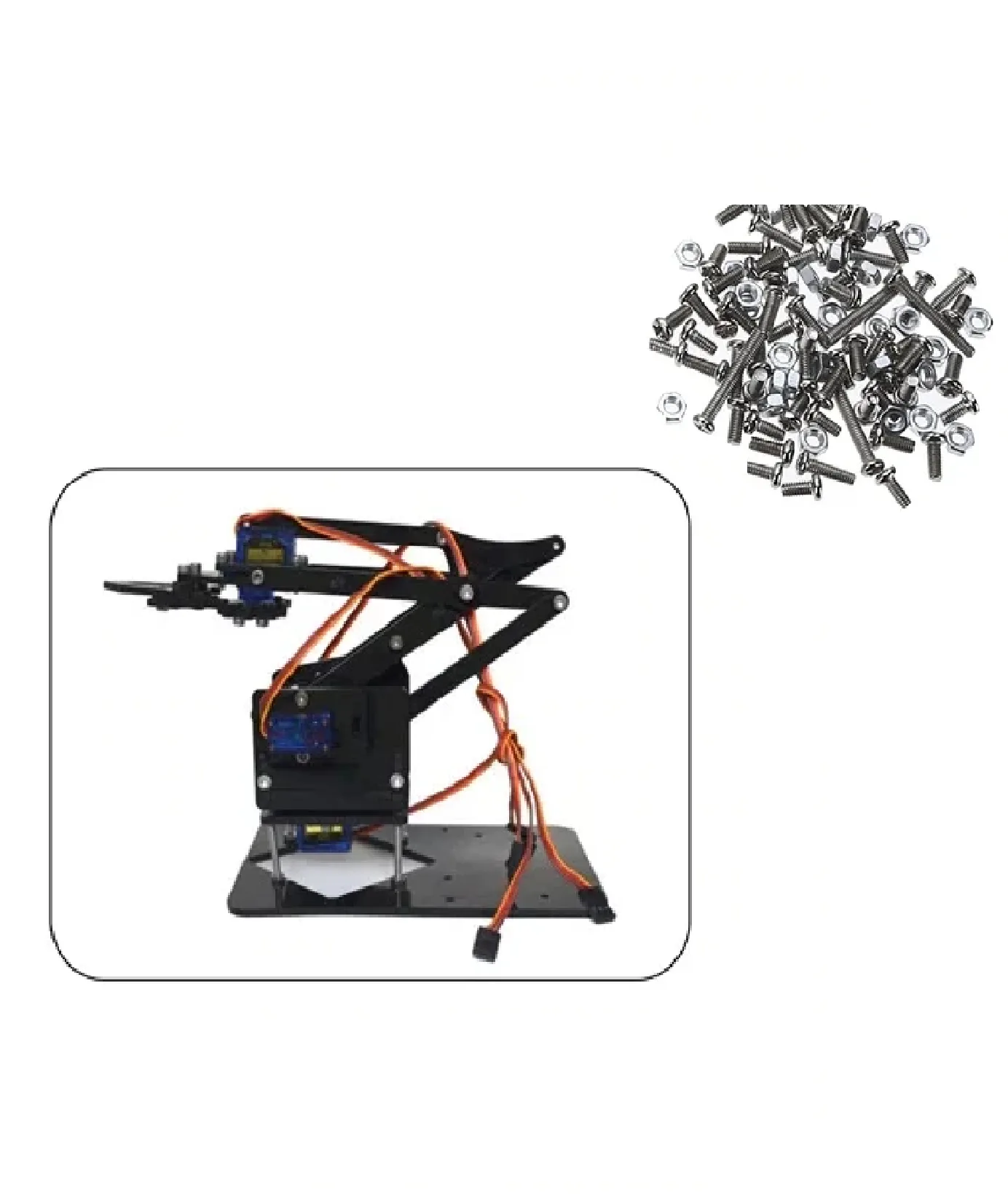
DIY Acrylic Robot Manipulator Mechanical Arm Kit
Full acrylic robot arm kit (servo and board sold separately). Provides the mechanical structure for your teleoperation arm — bring your own servos, controller, and wireless module.
Building the Transmitter (Controller Side)
Wire two joystick modules to Arduino Nano analog pins A0–A3 (X and Y axes of each joystick). Connect the nRF24L01 to SPI pins (D10–D13) with CE on D9 and CSN on D10. Use the RF24 library:
#include <RF24.h>
RF24 radio(9, 10);  // CE, CSN
uint8_t address[] = "ARM01";

struct ArmPacket {
  int16_t j1x, j1y;  // Shoulder + elbow
  int16_t j2x, j2y;  // Wrist + base
  uint8_t btn;        // Gripper state
};

void loop() {
  ArmPacket pkt;
  pkt.j1x = analogRead(A0) - 512;  // Center around 0
  pkt.j1y = analogRead(A1) - 512;
  pkt.j2x = analogRead(A2) - 512;
  pkt.j2y = analogRead(A3) - 512;
  pkt.btn = digitalRead(7);
  radio.write(&pkt, sizeof(pkt));
  delay(20);  // 50 Hz control rate
}
Building the Receiver (Robot Arm Side)
The receiver reads the radio packet and maps joystick values to servo PWM angles. Apply a deadband around zero to prevent arm drift when joysticks are centred:
void loop() {
  ArmPacket pkt;
  if (radio.available()) {
    radio.read(&pkt, sizeof(pkt));
    // Map joystick ±512 to ±30 degree increments
    if (abs(pkt.j1x) > 50) shoulder_angle += map(pkt.j1x, -512, 512, -3, 3);
    if (abs(pkt.j1y) > 50) elbow_angle   += map(pkt.j1y, -512, 512, -3, 3);
    shoulder_angle = constrain(shoulder_angle, 0, 180);
    elbow_angle    = constrain(elbow_angle,    0, 150);
    shoulder.write(shoulder_angle);
    elbow.write(elbow_angle);
  }
}
The incremental control mode (adding to current angle each cycle) gives smooth, natural arm movement. For one-to-one mapping (move joystick to 45° → arm goes to 45°), use absolute mapping mode instead.
Communication Protocol and Code
A robust teleoperation protocol needs three features:
- Heartbeat / watchdog — if no packet arrives for 500 ms, stop all motors and return arm to safe position. This prevents runaway if the transmitter loses power.
- Packet acknowledgement — nRF24L01 supports auto-ACK in hardware. Enable it to detect dropped packets without adding protocol overhead.
- Sequence numbers — add a 1-byte counter to each packet. If the receiver sees a gap, it can detect packet loss without waiting for a timeout.
// Watchdog in receiver loop
if (millis() - lastPacketTime > 500) {
  // Communication lost — safe shutdown
  shoulder.write(90); elbow.write(90);
  gripper.write(0);
}
Minimising Latency for Responsive Control
Every millisecond of unnecessary latency degrades operator feel. Key optimisations:
- Increase control rate to 100 Hz — reduce
delay()from 20 ms to 10 ms on the transmitter, verify the receiver loop completes in under 10 ms. - Use nRF24L01 1 Mbps mode — not 2 Mbps. Paradoxically, 1 Mbps is more reliable and less prone to retransmissions in noisy environments, reducing effective latency.
- Reduce payload size — smaller packets transmit faster. Pack four 10-bit joystick values into 5 bytes using bit fields.
- Disable Serial.print in production code — UART at 9600 baud takes 1 ms per character. A single debug line can add 10–20 ms per cycle.
- Place PA+LNA modules away from switching supplies — RF interference from motor drivers and DC-DC converters causes retransmissions. Use ferrite beads and physical separation.
Frequently Asked Questions
Can I use Wi-Fi instead of nRF24L01 for 100 m teleoperation?
Wi-Fi (ESP32 WebSocket) works but adds 20–80 ms of latency — acceptable for slow precision tasks, not ideal for dynamic control. The nRF24L01 PA+LNA achieves 1–5 ms latency at the same range, making it far better for real-time teleoperation.
How many servo axes can I control over one radio link?
With a 32-byte nRF24L01 payload, you can encode up to 16 servo positions (16-bit each) in a single packet — more than enough for a 6-DOF arm plus gripper. Use a struct and pack it cleanly for easy debugging.
Is a Flysky RC transmitter better than a custom joystick controller?
Flysky transmitters have ergonomic advantage — proper stick feel, spring centering, and trim adjustments built-in. For a custom feel (e.g., teaching pendant style), build your own with Arduino and joystick modules. Both are valid approaches.
Does the nRF24L01 need a license in India?
Devices operating in the 2.4 GHz ISM band at low power (under 1 W EIRP) are license-exempt in India under the WPC (Wireless Planning & Coordination) open spectrum policy. nRF24L01 modules at their default power setting are within these limits.
What is the maximum safe payload weight for a servo-based DIY robot arm at 100 m?
That depends entirely on the servo torque and arm geometry, not the wireless range. SG90 servos handle about 100 g at 5 cm from the joint. MG996R handles about 800 g. Plan your arm geometry and servo selection first, then add the wireless layer.
Ready to build your wireless teleoperation system? Shop Zbotic for robot arms, servos, RF modules, and RC transmitters — all with fast delivery across India. Take your robotics project to the next level today!


Add comment