
Managing power across multiple voltage rails simultaneously is a daily challenge in embedded systems, single-board computers, robotics, and industrial electronics. The INA3221 from Texas Instruments is a purpose-built three-channel power monitor that measures voltage, current, and calculates power on three independent rails with a single I2C connection. In this guide, you will learn everything about the INA3221 — its architecture, configuration, Arduino and Raspberry Pi integration, alert system, and practical multi-rail power monitoring projects.
What is the INA3221?
The INA3221 is a three-channel, high-side current and bus voltage monitor from Texas Instruments. It monitors shunt voltages across three external shunt resistors (one per channel) and three bus voltages, communicating all measurements over I2C with a single device address. The chip computes current from shunt voltage using Ohm’s law (V = IR) with 13-bit signed shunt voltage measurement and 13-bit bus voltage measurement per channel.
The INA3221 is designed for systems with multiple power rails — think a microcontroller board with 3.3V core, 5V peripheral, and 12V motor rails. Rather than using three separate INA219 chips (consuming 3 I2C addresses and requiring 3× the design effort), a single INA3221 handles all three channels with one device address, four configurable address pins, and a comprehensive alert system that can trigger on overvoltage, undervoltage, overcurrent, or power-sum limits.
You will find the INA3221 inside the NVIDIA Jetson Nano, inside many data center power management systems, and increasingly in high-end maker projects where detailed per-rail power budgeting is needed. It is also the sensor at the heart of several popular Raspberry Pi power management HATs.
Key Specifications
| Parameter | Value |
|---|---|
| Number of Channels | 3 |
| Bus Voltage Range | 0 to 26V |
| Bus Voltage Resolution | 8 mV LSB |
| Shunt Voltage Range | ±163.8 mV |
| Shunt Voltage Resolution | 40 µV LSB |
| Accuracy | ±0.5% (gain error), ±10 µV (offset) |
| Supply Voltage (VS) | 2.7V to 5.5V |
| Supply Current | 350 µA (operating) |
| Interface | I2C (100 kHz, 400 kHz, 1 MHz) |
| I2C Addresses | 0x40, 0x41, 0x42, 0x43 (configurable via A0, A1) |
| Alert Pins | 3 (ALERT1–3, open-drain, active-low) |
| Operating Temperature | -40°C to +125°C |
| Package | VSSOP-16 |
INA3221 vs INA219: Which to Choose?
The INA219 is widely used in maker projects for its simplicity and availability as breakout modules. Here is how the two compare:
| Feature | INA219 | INA3221 |
|---|---|---|
| Channels | 1 | 3 |
| Power Calculation | Hardware (onboard) | Software (compute V×I) |
| Bus Voltage Max | 26V | 26V |
| I2C Addresses | Up to 16 (A0, A1) | 4 (A0, A1) |
| Alert System | None | 3 independent alert pins + power-sum |
| Shunt Voltage ADC | 12-bit | 13-bit (signed) |
| Best For | Single-rail, simple projects | Multi-rail, production systems |
Use INA219 when you have one rail to monitor and need a simple module with existing library support. Use INA3221 when you have two or more rails, need hardware alerts, or are building a system that needs to track power budget compliance across multiple supply domains.
CJMCU-219 INA219 I2C Bi-directional Current/Power Monitoring Module
Start with the INA219 for single-channel power monitoring — it is widely supported, easy to use with Arduino, and available as a ready-to-use module for immediate prototyping.
Internal Architecture and Registers
Understanding the INA3221 register map helps you use it effectively. Key registers:
- Configuration Register (0x00): Enables/disables each channel, sets ADC resolution, sets operating mode (power-down, single-shot, continuous)
- Shunt Voltage Registers (0x01, 0x03, 0x05): 13-bit signed raw shunt voltage for channels 1, 2, 3 respectively
- Bus Voltage Registers (0x02, 0x04, 0x06): 13-bit unsigned raw bus voltage for channels 1, 2, 3
- Critical Alert Limit Registers (0x07, 0x09, 0x0B): Threshold that triggers ALERT pins immediately
- Warning Alert Limit Registers (0x08, 0x0A, 0x0C): Softer threshold for warning conditions
- Shunt Voltage Sum (0x0D): Sum of all enabled channel shunt voltages — useful for total current monitoring
- Shunt Sum Limit (0x0E): Threshold for total-power alert
- Mask/Enable Register (0x0F): Controls which conditions generate alerts
- Power Valid Upper/Lower (0x10, 0x11): Bus voltage thresholds for power-valid PV pin output
The shunt voltage LSB is 40 µV. For a 100 mΩ shunt resistor, the current resolution is 40 µV / 0.1 Ω = 400 µA per LSB, and full-scale (163.8 mV / 0.1 Ω) = 1.638A per channel. For higher current ranges, use a smaller shunt resistor (e.g., 10 mΩ gives 16.38A full-scale at 400 µA resolution).
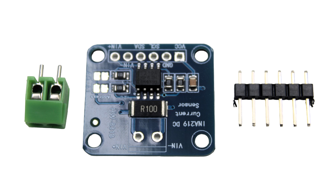
Wiring INA3221 with Arduino
The INA3221 breakout board (available from Adafruit, SparkFun, or as a Jetson Nano accessory) connects to Arduino via I2C plus shunt resistors on each channel:
| INA3221 Pin | Arduino Connection |
|---|---|
| VCC | 3.3V or 5V |
| GND | GND |
| SDA | A4 (SDA) |
| SCL | A5 (SCL) |
| A0, A1 | GND/GND → address 0x40 |
| ALERT1–3 | Optional: digital input with 10k pull-up to VCC |
For each channel, place a shunt resistor (commonly 100 mΩ for low currents, 10 mΩ for higher currents) in series with the power rail being monitored. Connect the high side of the shunt to IN+ and the low side to IN-. Connect V- (bus voltage sense) to the load side of the shunt. The INA3221 needs to see a stable bus voltage at the V- pin — this is the load supply voltage measurement point.
Arduino Code: Reading All Three Channels
Install the INA3221 library by teddokano or the Adafruit INA3221 library from the Arduino Library Manager.
#include <Wire.h>
#include <INA3221.h>  // teddokano/INA3221 library

// INA3221 address 0x40 (A0=GND, A1=GND)
INA3221 ina(INA3221_ADDR40_GND);

// Shunt resistor values in ohms for each channel
const float SHUNT_CHANNEL1 = 0.1;   // 100 mΩ
const float SHUNT_CHANNEL2 = 0.1;   // 100 mΩ
const float SHUNT_CHANNEL3 = 0.01;  // 10 mΩ (higher current rail)

void setup() {
  Serial.begin(115200);
  Wire.begin();

  ina.begin();
  // Enable all three channels
  ina.setChannelEnable(INA3221_CH1, ENABLE);
  ina.setChannelEnable(INA3221_CH2, ENABLE);
  ina.setChannelEnable(INA3221_CH3, ENABLE);

  // Set averaging to reduce noise (16 samples)
  ina.setAveragingMode(INA3221_AVG16);

  Serial.println("INA3221 Triple-Channel Power Monitor Ready");
  Serial.println("Ch1: 3.3V Rail | Ch2: 5V Rail | Ch3: 12V Rail");
}

void loop() {
  Serial.println("n=== Power Monitor Reading ===");

  for (int ch = 1; ch <= 3; ch++) {
    INA3221_ch_t channel = (INA3221_ch_t)(ch - 1);
    float shuntV = ina.getShuntVoltage(channel);    // in V
    float busV = ina.getBusVoltage(channel);         // in V
    float shuntR = (ch == 1) ? SHUNT_CHANNEL1 :
                   (ch == 2) ? SHUNT_CHANNEL2 : SHUNT_CHANNEL3;
    float current = shuntV / shuntR;                 // Ohm's law
    float power = busV * current;                    // Watts

    Serial.print("Channel "); Serial.print(ch); Serial.println(":");
    Serial.print("  Bus Voltage: "); Serial.print(busV, 3); Serial.println(" V");
    Serial.print("  Shunt Voltage: "); Serial.print(shuntV * 1000, 3); Serial.println(" mV");
    Serial.print("  Current: "); Serial.print(current * 1000, 2); Serial.println(" mA");
    Serial.print("  Power: "); Serial.print(power * 1000, 2); Serial.println(" mW");
  }

  delay(1000);
}
Using INA3221 with Raspberry Pi
The INA3221 is native to the Jetson Nano where the Linux kernel includes a built-in driver. On Raspberry Pi, you can use it via Python:
pip3 install pi-ina3221

from ina3221 import INA3221

INA = INA3221(shunt_resistor=[0.1, 0.1, 0.01])
INA.configure(average=INA3221.AVERAGE_16_SAMPLES)

for ch in [1, 2, 3]:
    bus_v = INA.get_bus_voltage(ch)
    current_mA = INA.get_current(ch)
    power_mW = INA.get_power(ch)
    print(f"Channel {ch}: {bus_v:.3f}V | {current_mA:.1f}mA | {power_mW:.1f}mW")
On Jetson Nano, INA3221 data is exposed via the sysfs interface at /sys/bus/i2c/drivers/ina3221/. You can read it directly:
cat /sys/bus/i2c/drivers/ina3221/0-0040/iio:device0/in_voltage0_input
# Returns bus voltage in mV for channel 1

cat /sys/bus/i2c/drivers/ina3221/0-0040/iio:device0/in_current0_input
# Returns current in mA for channel 1
Alert and Warning System
The INA3221’s three ALERT pins (open-drain, active-low, require external pull-up) provide hardware-level power monitoring without MCU polling:
- Critical Alert: Triggers when shunt voltage exceeds the Critical Alert Limit Register value. Latched — clears by reading the Mask/Enable register.
- Warning Alert: Triggers when the rolling average of shunt voltage exceeds the Warning Alert Limit. Useful for sustained overcurrent detection (vs. brief transient spikes that trigger Critical).
- Timing Alert: Triggers when the conversion time of any channel exceeds a configured timeout.
- Power Valid (PV): Goes high when all enabled bus voltages are within the Power Valid Upper and Lower limit registers. Perfect for system power-good sequencing logic.
- Sum Alert: Triggers when the sum of all enabled shunt voltages exceeds the Shunt Sum Limit register — effectively a total power budget alarm.
Example: Set Critical Alert Limit for channel 2 (5V rail) to protect a 2A-rated load. With a 100 mΩ shunt, 2A = 200 mV shunt voltage = 5000 raw counts (200 mV / 40 µV). Write 5000 to register 0x09. When the load draws more than 2A, ALERT2 goes low, waking your MCU via interrupt to take protective action (shut down the rail, log the event, send a notification).
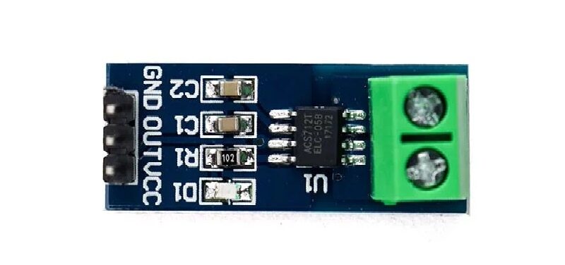
5A Range Current Sensor Module ACS712
For lower-current isolated monitoring (up to 5A), the ACS712 5A module offers Hall-effect isolation — a great companion for the INA3221 in mixed-isolation power monitoring systems.
Multi-Rail Power Monitoring Projects
Raspberry Pi Cluster Power Monitor
A Raspberry Pi cluster running Docker or Kubernetes has multiple power domains: 5V main supply, PoE rail, and USB peripheral rail. Use an INA3221 on a HAT to monitor all three simultaneously. Log per-rail wattage to InfluxDB, visualize in Grafana, and set critical alerts to detect nodes with failing power supply units before they cause data corruption.
Robotics Servo and Motor Rail Monitor
A typical robot has 3.3V logic, 5V servo rail, and 12V motor driver rail. An INA3221 on the main controller board monitors all three rails continuously. When motor current spikes (stall detection), the ALERT3 interrupt fires and the MCU cuts power to the motor before the H-bridge overheats. Log energy per channel to compute battery state of charge for autonomous mission planning.
Solar MPPT System Multi-Rail Monitor
Monitor panel input current/voltage (CH1), battery charge current (CH2), and load output current (CH3) using INA3221. Calculate panel power, battery state of charge, and load power simultaneously. Use the Sum Alert to detect when total system power budget is exceeded (e.g., inverter overload condition). Display all three channels on a small LCD with trend graphs.
Development Board Power Profiling
During embedded firmware development, understanding which peripherals consume power is critical for battery life optimization. Use the INA3221 to break out the 3.3V, 5V, and VBat rails of your development board, then trigger firmware state transitions while logging per-rail current. Identify which code paths or peripheral activations cause unexpected power spikes.
Power Sequencing and Rail Supervision
One of the most valuable but underused INA3221 features is its Power Valid output. In multi-rail systems, power rails must often come up in a specific sequence — for example, VDDIO must be stable before VDD_CORE powers up, or the FPGA configuration RAM must see 3.3V before the FPGA itself gets 1.0V core power. Incorrect sequencing can damage ICs.
Configure the INA3221’s Power Valid Upper Limit registers to define the minimum acceptable voltage for each rail (e.g., 3.0V for a 3.3V rail, 4.7V for a 5V rail). When all three monitored rails are within their valid ranges, the PV pin goes high. Use PV as the enable signal for the next stage in your power sequencing tree — this creates hardware-enforced sequencing without complex supervisory MCU firmware.
Troubleshooting Common Issues
- All channels read zero current: Check shunt resistors are actually in the current path. Verify IN+ is on the high side (supply side) and IN- is on the load side of the shunt.
- Bus voltage reads correctly but current is wrong: Shunt resistor value in your code must exactly match the physical shunt installed. Double-check your shunt resistance and update the constant.
- I2C device not found: Verify A0/A1 pin states match the address you are using. Check for 3.3V vs 5V compatibility — use logic level shifter if needed.
- Negative current readings when expecting positive: You have IN+ and IN- swapped on that channel. Reverse the shunt resistor connection or negate the reading in software.
- ALERT pins never trigger: Alert pins are open-drain — they need external pull-up resistors (typically 10kΩ to VCC). Also verify you have written the correct threshold values to the limit registers and enabled the alert in the Mask/Enable register.
- Readings noisy on high-current channel: Increase averaging (16, 64, or 128 samples). Add a small capacitor (100 nF) across the shunt resistor to filter switching noise from DC-DC converters.
Frequently Asked Questions
A: The INA3221 bus voltage input accepts 0–26V. For negative rails, the common approach is to measure the absolute value by placing the INA3221 between the negative rail and the most negative potential (GND), treating it as a positive voltage relative to its own reference. For true negative voltage monitoring, use the INA190 or add a voltage inversion circuit.
A: Calculate as: Shunt R = 163.8 mV (max shunt voltage) / Maximum expected current. For 1A max: 163.8 mΩ (use 100 mΩ for headroom). For 10A max: 16.38 mΩ (use 10 mΩ). Always use 1% tolerance or better resistors rated for the power dissipation (P = I² × R).
A: Yes. Connect the battery’s positive terminal to IN+, a shunt resistor in the charge/discharge path, and the load side of the shunt to IN- and the Bus Voltage (V-) pin. You can monitor both charge current (positive) and discharge current — however the INA3221 shunt input is not bidirectional in the traditional sense; it only measures positive shunt voltage. For charge/discharge monitoring, pair with the INA219 which handles negative shunt voltages.
A: Up to 4 INA3221 chips (addresses 0x40, 0x41, 0x42, 0x43), giving you 12 total monitored channels on a single I2C bus. For more, use a TCA9548A I2C multiplexer to connect additional devices.
A: The Jetson Nano uses an INA3221 to monitor three power rails: VDD_IN (main power), VDD_GPU (GPU core), and VDD_CPU (CPU core). NVIDIA’s power management framework reads these values to implement software-defined power limits (5W and 10W modes) and thermal throttling decisions based on actual measured power consumption.
Build Your Multi-Rail Power Monitoring System
Explore Zbotic’s full selection of power monitoring sensors, current sensors, and measurement modules — with fast shipping across India for your next electronics project.


Add comment