
The I2C protocol is one of the most widely used communication protocols in embedded electronics. Whether you are connecting an OLED display, reading a temperature sensor, or interfacing an accelerometer, there is a good chance I2C is doing the heavy lifting. In this guide, we will explain exactly how I2C works — from the physical SDA and SCL lines all the way to addressing, clock stretching, and multi-device buses.
By the end, you will have a thorough understanding of I2C and the confidence to connect multiple I2C devices to a single Arduino or microcontroller without confusion.
What Is I2C?
I2C (Inter-Integrated Circuit, pronounced “eye-squared-see” or “eye-two-see”) is a synchronous, multi-master, multi-slave, packet-switched serial communication protocol invented by Philips Semiconductor (now NXP) in 1982. It was originally designed to allow microcontrollers to communicate with peripheral chips on the same circuit board using just two wires.
The protocol has since become a global standard and is implemented in thousands of chips — displays, sensors, memory devices, ADCs, DACs, real-time clocks, and more. Its two-wire design makes PCB routing and wiring simple, which is a major reason for its enduring popularity.
Key Features of I2C
- Only 2 wires: SDA (data) and SCL (clock) — plus ground
- Multi-device: Up to 127 devices on a single bus (7-bit addressing)
- Bidirectional data: Both master and slave can send and receive on the same SDA line
- Synchronous: Data is clocked by SCL — no baud rate to match
- Addressed: Every device has a unique address — no chip-select lines needed
SDA and SCL: The Two Wires Explained
The entire I2C bus runs on just two signal lines:
SDA — Serial Data Line
SDA carries the actual data bits between master and slave. It is bidirectional — the same wire is used by both the master (sending commands and addresses) and the slave (sending data back). At any given moment, only one device is driving the SDA line; the other device listens. This is made possible by the open-drain (or open-collector) design of I2C — more on this below.
SCL — Serial Clock Line
SCL carries the clock signal generated by the master. Every rising edge of SCL signals that the current SDA bit is valid and should be sampled. Every falling edge signals that SDA may change to prepare the next bit. The master controls the clock, so all communication is synchronised to its rhythm. A slave can slow the master down using clock stretching (covered later).
Open-Drain Architecture
Both SDA and SCL are open-drain lines. This means each device on the bus can only pull the line LOW (by connecting it to ground through a transistor) or release it (by putting the transistor in a high-impedance state). The lines are pulled HIGH by external pull-up resistors when no device is pulling them low.
This architecture is what allows multiple devices to share the same wire without conflict. If two devices try to communicate simultaneously and one pulls LOW while the other releases, the LOW wins — this is called wired-AND behaviour and is integral to I2C’s arbitration mechanism.
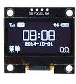
1.3 Inch I2C/IIC 128×64 OLED Display Module 4pin
A perfect I2C device to practice with — this OLED display connects with just SDA, SCL, VCC and GND. Great for Arduino projects.
I2C Addressing: How Devices Are Identified
Every I2C device has a 7-bit address (some newer devices use 10-bit addressing, but 7-bit is by far the most common). With 7 bits, you can address up to 2^7 = 128 unique addresses, though a few are reserved — giving you 112 usable addresses in practice.
How Addresses Are Set
Addresses are typically partly fixed (built into the chip) and partly configurable. Many I2C sensors have 1 or 2 address pins (often labelled ADR or A0/A1) that you connect to VCC or GND to set the lower address bits. For example, the popular PCF8574 I/O expander has 3 address pins, giving 8 possible addresses on the same bus — so you can have 8 of them simultaneously.
7-Bit vs 10-Bit Addressing
Standard I2C uses 7-bit addresses. The 10-bit addressing mode was introduced in I2C v2.0 for applications needing more than 112 devices on a single bus, but it is rare in practice. Most hobbyist and industrial sensors use 7-bit addressing.
Common I2C Addresses
- 0x3C / 0x3D: SSD1306 OLED displays
- 0x68 / 0x69: MPU-6050 gyroscope/accelerometer
- 0x76 / 0x77: BME280 temperature/humidity/pressure sensor
- 0x57: AT24C EEPROM chips
- 0x48–0x4B: ADS1115 ADC
The I2C Communication Process Step by Step
Here is exactly what happens when a master communicates with a slave over I2C:
Step 1: Start Condition
The master generates a Start condition by pulling SDA LOW while SCL is HIGH. This is the unique signal that wakes all slaves and tells them communication is beginning. Normally, SDA only changes when SCL is LOW — so an SDA falling edge while SCL is HIGH is unmistakably a Start.
Step 2: Address Frame
The master sends the 7-bit address of the target slave, followed by a 1-bit Read/Write (R/W) flag. A 0 means the master will write data to the slave; a 1 means the master wants to read from the slave. All 8 bits are clocked out MSB-first on SDA, each bit valid on a rising SCL edge.
Step 3: Acknowledge (ACK)
After the 8-bit address frame, the master releases SDA and generates one more SCL pulse. The addressed slave — if it recognised its address — pulls SDA LOW to send an ACK (Acknowledge). If SDA stays HIGH, it is a NACK (Not Acknowledge), meaning no device responded. The master then decides whether to retry or abort.
Step 4: Data Frames
One or more 8-bit data frames follow, each acknowledged by the receiver. In write mode, the master sends data and the slave ACKs. In read mode, the slave sends data and the master ACKs (or NACKs the last byte to signal it is done reading).
Step 5: Stop Condition
The master generates a Stop condition by releasing SDA HIGH while SCL is HIGH. This signals the end of the transaction. All slaves return to listening mode, waiting for the next Start.
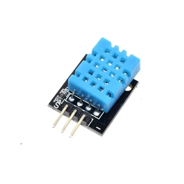
DHT11 Digital Relative Humidity and Temperature Sensor Module
A popular sensor for Arduino projects — pair it with an I2C OLED to display real-time temperature and humidity readings.
Pull-Up Resistors: Why They Are Essential
Since I2C lines are open-drain, they cannot pull themselves HIGH. External pull-up resistors are mandatory — without them, the lines float and communication is impossible or unreliable.
Choosing the Right Pull-Up Value
Typical values are 4.7kΩ for 100kHz operation and 2.2kΩ or 1kΩ for 400kHz. The correct value depends on:
- Bus capacitance: Longer wires and more devices increase capacitance, requiring lower resistance to charge the line faster
- Operating voltage: 3.3V systems need different values than 5V systems
- Bus speed: Faster speeds need lower resistance to meet rise time requirements
Too high a resistance causes slow rise times and communication errors. Too low a resistance increases current draw and can overload slave output drivers. A starting value of 4.7kΩ works well for most short-bus (under 1m) applications at 100kHz.
Note: Many breakout boards (like the OLED module above) include pull-up resistors on the PCB. If you have multiple modules on the same bus, each with their own pull-ups, the effective resistance decreases — this is generally fine unless you have many modules.
Clock Stretching
Clock stretching is a mechanism that allows a slave device to pause the I2C clock when it needs more time to process data. The slave holds SCL LOW after the master releases it, preventing the master from generating more clock pulses until the slave is ready.
Not all master implementations support clock stretching. Bit-banged I2C implementations on microcontrollers often do not poll SCL after releasing it. If you use a sensor that stretches the clock and your master does not support it, you will see communication errors or garbled data.
Hardware I2C peripherals on chips like the ATmega328 (Arduino Uno) and STM32 series fully support clock stretching.
I2C Speeds: Standard, Fast, and High Speed
| Mode | Speed | Introduced In |
|---|---|---|
| Standard Mode (Sm) | 100 kbit/s | Original spec (1982) |
| Fast Mode (Fm) | 400 kbit/s | I2C v1.0 (1992) |
| Fast Mode Plus (Fm+) | 1 Mbit/s | I2C v2.1 (2000) |
| High Speed Mode (Hs) | 3.4 Mbit/s | I2C v2.0 (1998) |
| Ultra Fast Mode (UFm) | 5 Mbit/s | I2C v3.0 (2007) |
For most Arduino and hobbyist projects, Standard Mode (100kHz) or Fast Mode (400kHz) is sufficient. The Wire library on Arduino defaults to 100kHz; you can switch to 400kHz by calling Wire.setClock(400000).
Connecting Multiple I2C Devices
One of I2C’s greatest strengths is the ability to put many devices on a single bus. All devices share the same SDA and SCL lines — you simply wire them in parallel:
Arduino          OLED (0x3C)    Sensor (0x48)   EEPROM (0x57)
  A4 (SDA) ------+----------+----------+----------
  A5 (SCL) ------+----------+----------+----------
  5V       ------+----------+----------+----------
  GND      ------+----------+----------+----------
                4.7k pull-up resistors to 5V on SDA and SCL
Handling Address Conflicts
The most common challenge with multiple I2C devices is address conflicts. If two devices have the same address, the bus cannot distinguish between them. Solutions include:
- Use the device’s address pins (if available) to change one device’s address
- Use an I2C multiplexer like the TCA9548A, which gives you 8 separate I2C channels switchable by address
- Use software I2C on alternative pins (bit-banging) for one device
Using I2C with Arduino
Arduino’s built-in Wire library makes I2C simple. Here is a complete example scanning for all connected I2C devices — every newcomer should run this first:
#include <Wire.h>

void setup() {
  Wire.begin();
  Serial.begin(9600);
  Serial.println("I2C Scanner");

  for (byte addr = 1; addr < 127; addr++) {
    Wire.beginTransmission(addr);
    byte error = Wire.endTransmission();
    if (error == 0) {
      Serial.print("Device found at 0x");
      if (addr < 16) Serial.print("0");
      Serial.println(addr, HEX);
    }
  }
  Serial.println("Scan complete.");
}

void loop() {}
Connect your I2C devices, upload this sketch, and open the Serial Monitor. You will see the address of every device on the bus — an invaluable debugging tool.
Writing Data to an I2C Device
Wire.beginTransmission(0x3C);  // Start transmission to address
Wire.write(0x00);               // Control byte
Wire.write(0xAE);               // Command byte (e.g., display off)
Wire.endTransmission();         // Send Stop condition
Reading Data from an I2C Device
Wire.beginTransmission(0x48);   // Address the device
Wire.write(0x00);               // Register to read from
Wire.endTransmission(false);    // Repeated Start (not Stop)
Wire.requestFrom(0x48, 2);      // Request 2 bytes
int high = Wire.read();
int low  = Wire.read();
10CM Male To Female Breadboard Jumper Wires – 40Pcs
Connect I2C sensor modules (with female headers) to your Arduino’s male header pins cleanly and reliably.
I2C vs SPI: When to Use Which
| Feature | I2C | SPI |
|---|---|---|
| Wires | 2 (SDA + SCL) | 4+ (MOSI, MISO, SCK, CS) |
| Speed | Up to 3.4 Mbit/s | Up to 50+ Mbit/s |
| Multiple slaves | Address-based, no extra wires | One CS pin per slave |
| Full duplex | No (half duplex) | Yes |
| Best for | Many slow sensors on one bus | Fast, high-bandwidth devices |
Use I2C when wiring simplicity matters and speed is not critical — sensors, displays, EEPROMs, and RTCs are typical I2C devices. Use SPI when you need maximum speed — SD cards, TFT displays, and ADCs often prefer SPI.
Frequently Asked Questions
What is the maximum number of devices on an I2C bus?
With standard 7-bit addressing, I2C supports up to 112 usable device addresses (128 minus reserved addresses). However, the practical limit is also constrained by bus capacitance — the total capacitance of the bus (wires + devices) should not exceed 400pF at Standard or Fast mode. An I2C multiplexer like the TCA9548A can extend this by creating separate bus segments.
Why does I2C need pull-up resistors?
I2C lines use open-drain outputs — devices can only pull lines LOW, not HIGH. Pull-up resistors provide the path for the lines to return HIGH when no device is pulling them low. Without pull-ups, the lines cannot reach a valid HIGH state and the bus will not work. Typical values are 4.7kΩ for 100kHz and 2.2kΩ for 400kHz.
What pins are SDA and SCL on Arduino Uno?
On the Arduino Uno (ATmega328P), SDA is pin A4 and SCL is pin A5. These are also labelled on the board near the analog header. The same signals are also available on the dedicated SDA/SCL header near the power header (added in the Arduino Uno R3 and later). For Wire library use, you do not need to manually configure these pins — just call Wire.begin().
What is a repeated start in I2C?
A repeated start (also called restart) is when the master generates a new Start condition without first sending a Stop. This allows the master to switch from write to read mode within a single atomic transaction — useful for write-then-read operations like writing a register address and immediately reading back its value. In Arduino Wire library, this is done by passing false to endTransmission(), then calling requestFrom().
Can 3.3V and 5V I2C devices share the same bus?
Not directly — you risk damaging 3.3V devices if 5V signals are applied. You need a level shifter between the two voltage domains. A bidirectional level shifter using N-channel MOSFETs (like the BSS138) works well for I2C because it supports the open-drain nature of the bus. Many breakout modules include onboard level shifters, so check the module datasheet first.
Ready to Build Your First I2C Project?
Zbotic stocks I2C-compatible OLED displays, sensors, and all the jumper wires, resistors, and prototyping gear you need. Start building with I2C today.


Add comment