
Pixhawk is the most widely used open-source flight controller in the world, and ArduPilot is the firmware that makes it truly powerful. Together, they power everything from DIY quadcopters and fixed-wing planes to professional agricultural sprayers and autonomous research platforms. In India, the combination is especially popular among engineering students, drone-kit builders, and hobbyist pilots who want full control over their aircraft’s behaviour.
But the setup process can feel intimidating the first time. There are firmware choices, calibration sequences, parameter trees with thousands of entries, and safety checks that must pass before you can arm. This guide walks you through the complete ArduPilot Pixhawk configuration process — from unboxing to first flight — in clear, step-by-step language.
What You Need Before You Start
Before touching Mission Planner, make sure you have the following ready:
- Pixhawk flight controller (Pixhawk 4, Cube Orange, Holybro Pixhawk 6C, or compatible clone)
- USB micro cable (good quality — cheap cables cause connection failures)
- Windows PC (Mission Planner is Windows-native; Linux/Mac users can use QGroundControl instead)
- GPS module with compass (u-blox M8N or M9N recommended)
- RC receiver (SBUS, PPM, or CRSF-compatible)
- ESCs and motors (PWM, DSHOT, or UAVCAN)
- Telemetry radio pair (optional but highly recommended for tuning)
- Power module (3DR-compatible, for voltage/current sensing)
- LiPo battery (matched to your motor/ESC combination)

3DR 100mW Radio Telemetry 915MHz For APM PX4 Pixhawk
The classic 3DR SiK telemetry radio pair — plug-and-play with Mission Planner. Gives you real-time parameter tuning, live data display, and ground station control up to 300 m range.
View on Zbotic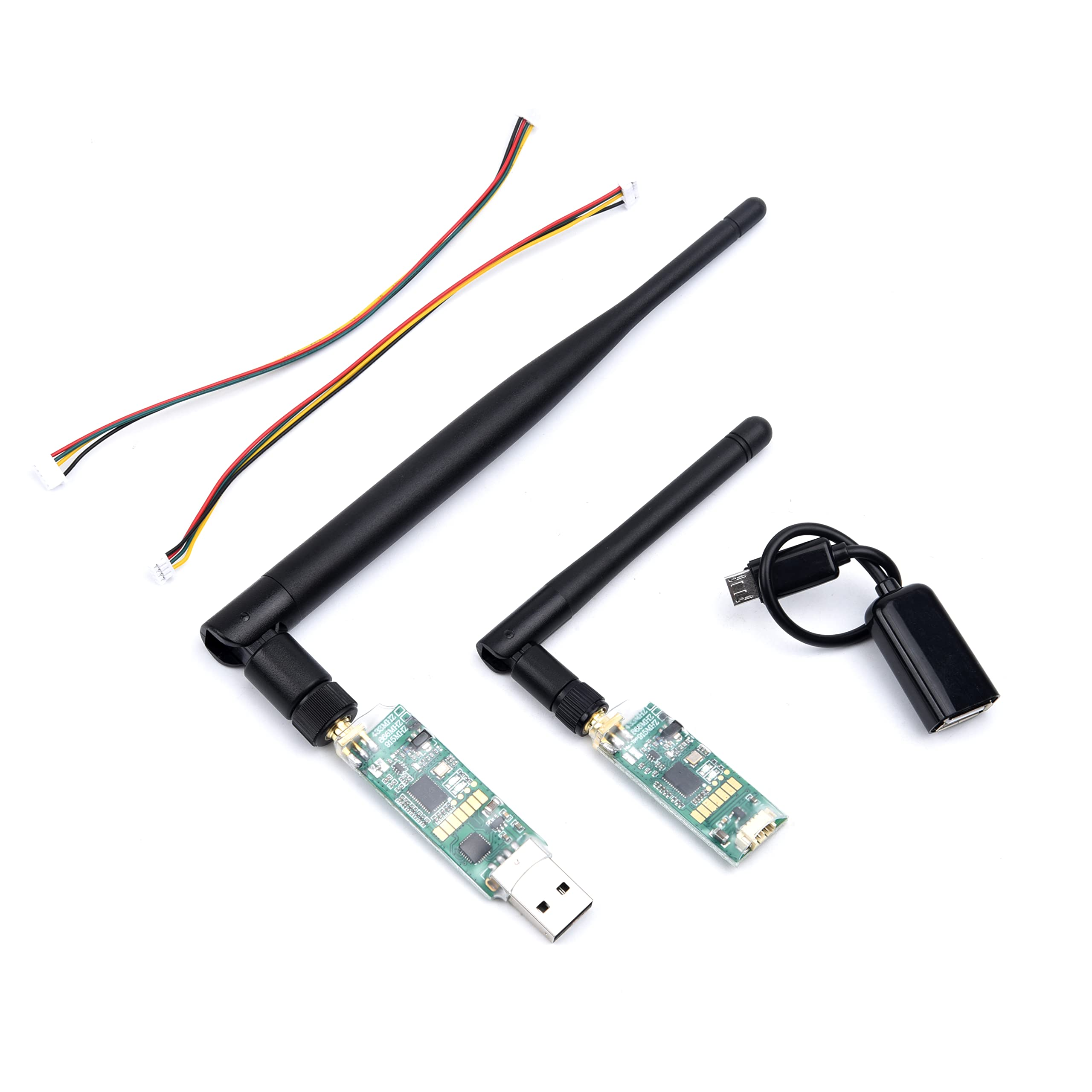
3DR Single TTL MINI Radio Telemetry 433MHz 500mW for Pixhawk and APM
A compact 433 MHz telemetry module for longer ground penetration. Ideal for flying in or near structures where 915 MHz signals degrade. 500 mW output gives extended range.
View on ZboticInstalling Mission Planner
Mission Planner is the primary ground control station (GCS) for ArduPilot. It handles firmware flashing, calibration, parameter editing, mission planning, and live telemetry display.
- Go to ardupilot.org/planner and download the latest Mission Planner installer (.msi).
- Run the installer and accept the default installation path.
- Install the required drivers when prompted — these are the Silicon Labs CP2102 USB-to-UART drivers needed to communicate with the Pixhawk.
- Launch Mission Planner. You will see the HUD (Heads-Up Display) screen by default.
- Do not connect the Pixhawk yet — wait until the firmware flashing step.
Alternative for Linux/Mac: QGroundControl (QGC) supports ArduPilot and PX4 on all platforms. Most of the steps below apply to QGC with minor UI differences.
Flashing ArduPilot Firmware
ArduPilot comes in several vehicle-specific builds. For a quadcopter, you want ArduCopter. For fixed-wing, use ArduPlane. For rovers, ArduRover.
- Connect your Pixhawk to the PC using the USB cable. Do not connect the battery during firmware flash.
- In Mission Planner, go to Setup → Install Firmware.
- Mission Planner will auto-detect your board. If it doesn’t, select your board manually from the dropdown.
- Click the quadcopter icon (or your vehicle type). Mission Planner downloads and flashes the latest stable ArduCopter release.
- Wait for the “Upload Complete” confirmation. The Pixhawk will reboot.
- After reboot, connect at the top right of Mission Planner: select the correct COM port and set baud rate to 115200. Click Connect.
Pro tip: Always use stable releases for actual flight. Beta/latest builds are for testing only and may have known issues.
Wiring the Pixhawk
Wiring is where many beginners make mistakes. Here is the standard quadcopter wiring order:
Motor/ESC Numbering
ArduCopter uses a specific motor layout. For a standard X-quad looking from above:
- Motor 1: Front Right (CCW)
- Motor 2: Rear Left (CCW)
- Motor 3: Front Left (CW)
- Motor 4: Rear Right (CW)
Connect ESC signal wires to Pixhawk’s MAIN OUT ports 1–4 respectively. Ground wires should all connect (the Pixhawk needs a common ground even if it doesn’t take ESC power).
GPS and Compass
Connect the GPS module to the GPS port (UART + I2C combined connector on Pixhawk 4/6C). Mount the GPS as high and as far forward from the power distribution board as possible — ESC switching noise is the #1 cause of compass interference.
RC Receiver
SBUS receivers connect to the RC IN port. PPM receivers connect to the PPM pin. ExpressLRS/CRSF receivers use a UART (typically SERIAL4) with CRSF protocol selected in ArduPilot parameters.
Power Module
Connect the power module between your LiPo battery XT60 and the PDB/ESC. The 6-pin JST connector goes to Pixhawk’s POWER port. This provides regulated 5.3 V to the Pixhawk and feeds voltage/current ADC readings.
Telemetry Radio
Connect the air-side telemetry radio to TELEM1 (default for MAVLink output). Connect the ground-side radio to your PC USB before launching Mission Planner.
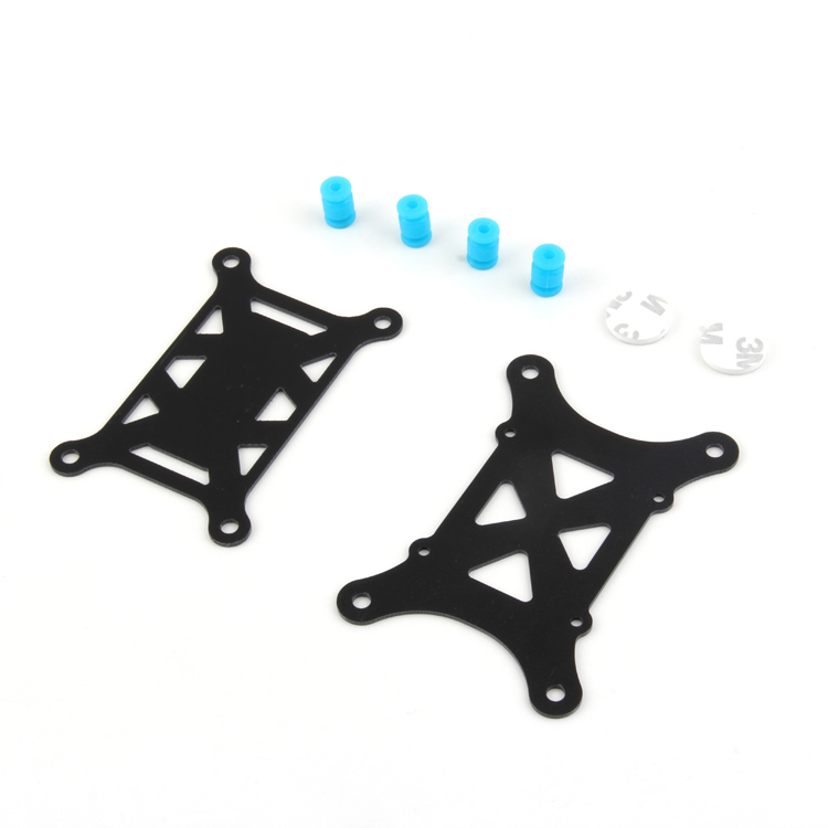
Anti-Vibration Shock Absorber for APM/KK/MWC/PixHawk
Soft silicone damping balls that isolate the Pixhawk from prop vibrations. Prevents gyro aliasing and barometer noise — one of the most impactful upgrades for clean ArduPilot performance.
View on ZboticInitial Setup Wizard
Once connected in Mission Planner, navigate to Setup → Mandatory Hardware. This section contains all the calibration steps you must complete before ArduPilot will allow arming.
Frame Type
Go to Frame Type and select your configuration. For a standard + or X quad, select the appropriate icon. For H-frames, Y6, Octocopters, etc., select accordingly. Click Apply. The Pixhawk will reboot with the correct motor mixing applied.
Flight Controller Orientation
Under Accel Calibration → Board Orientation, set the rotation of your Pixhawk relative to the drone’s nose-forward direction. If your Pixhawk is mounted sideways or reversed, select the appropriate rotation (ROTATION_YAW_90, ROTATION_ROLL_180, etc.).
Sensor Calibration
Accelerometer Calibration
- Go to Setup → Mandatory Hardware → Accel Calibration.
- Click Calibrate Accel. Mission Planner will prompt you to place the Pixhawk in 6 orientations: level, nose down, nose up, left side down, right side down, and on its back.
- Hold each position still and click “Click when done” after each orientation.
- After the 6th position, click “Done” and wait for calibration to complete.
Important: Do this on a flat, level surface. Even 1–2 degrees of tilt in the “level” position will cause your drone to drift when hovering.
Compass Calibration
- Go to Setup → Mandatory Hardware → Compass.
- Ensure the GPS/compass module is selected as the primary compass (not the internal compass, which is noisier).
- Click Start next to OnBoard Mag Calibration.
- Rotate the entire drone slowly in all axes — think of drawing a sphere with each arm. Continue until all progress bars reach 100%.
- Click Accept and check that the offsets are reasonable (below 400 on each axis; if they exceed 600, you have magnetic interference — move the GPS further from ESCs/battery).
Barometer and Airspeed
The barometer calibrates automatically on each boot. Cover the Pixhawk’s barometer vent with foam to prevent wind errors — this is critical for accurate altitude hold. The stock foam on most Pixhawk boards is sufficient but can degrade over time.
Radio Calibration
- Turn on your RC transmitter and bind it to your receiver before proceeding.
- In Mission Planner, go to Setup → Mandatory Hardware → Radio Calibration.
- Click Calibrate Radio. Move all sticks to their full extents — up/down, left/right — and move all switches through their full range.
- Click Click when done. Mission Planner records min/max values for all channels.
- Verify that your transmitter mode (Mode 1 or Mode 2) matches your stick layout. Most Indian pilots use Mode 2 (throttle on left).
Stick deadband: For smooth Loiter and AltHold performance, set your RC deadband to 30–50 in the Mission Planner parameters (RCMAP parameters).
Configuring Flight Modes
ArduCopter supports many flight modes. The recommended beginner setup uses 6 modes on a 3-position + 2-position switch combination:
| Mode | What It Does | Recommended For |
|---|---|---|
| Stabilize | Self-levelling, no position hold | Manual control, wind |
| AltHold | Altitude locked, no position hold | Practice, beginners |
| Loiter | GPS position + altitude hold | Hovering, photography |
| Auto | Executes pre-planned missions | Mapping, surveys |
| RTL | Return to launch point | Failsafe, lost orientation |
| Land | Descend and disarm automatically | Failsafe |
Configure modes at Setup → Mandatory Hardware → Flight Modes. Assign each switch position to a mode. Always put RTL on an easy-to-reach switch.
Setting Up Failsafe
Failsafe is the behaviour ArduPilot executes when it loses RC signal or battery gets critically low. Configuring failsafe correctly prevents fly-aways and crashes.
RC Failsafe
Go to Config → Full Parameter List and set:
- FS_THR_ENABLE = 1 (enable throttle failsafe)
- FS_THR_VALUE = 10 below your lowest throttle PWM value (typically 975 if your min throttle is 985)
- FS_THR_ACTION = 1 (RTL on RC loss) or 2 (Land) — RTL is safer for open fields
Battery Failsafe
- FS_BATT_ENABLE = 1
- FS_BATT_VOLTAGE = 3.5 V per cell × number of cells (e.g., 14.0 V for a 4S pack)
- FS_BATT_ACTION = 2 (Land) — prevents fly-away but ensures a controlled descent
GCS Failsafe
If you are using telemetry, also enable GCS failsafe (FS_GCS_ENABLE = 1) so the drone RTLs if it loses contact with Mission Planner during Auto missions.
ESC Calibration and Motor Test
ESC Calibration (PWM ESCs)
If using standard PWM ESCs (not DSHOT), each ESC must learn your throttle range. In Mission Planner:
- Go to Setup → Optional Hardware → Motor Test.
- Alternatively, use the manual ESC calibration: disconnect battery, set throttle max, connect battery, wait for beeps, lower throttle, wait for confirmation beeps.
- If using DSHOT ESCs, skip ESC calibration entirely — DSHOT is a digital protocol and doesn’t need PWM range calibration.
Motor Test
- Remove all propellers before testing motors.
- Connect the battery. In Mission Planner, go to Setup → Optional Hardware → Motor Test.
- Test each motor individually at 5% throttle. Verify the correct motor spins (check ArduCopter motor diagram for your frame).
- Check spin direction. Motors on diagonal pairs should spin the same direction. If wrong, swap any two of the three motor wires to the ESC.
- After confirming directions, install propellers with correct CW/CCW orientation per the motor map.
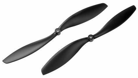
1045 2 Blades Carbon Fiber Propeller CW & CCW
Stiff 10-inch carbon fiber propellers for quadcopter builds. The CW/CCW pair is essential — each motor needs the correct rotation direction prop to balance torque correctly on the ArduCopter motor map.
View on ZboticPre-Flight Checklist and First Flight
Before your first flight, run through this checklist every time:
- [ ] Props tight and correct orientation (CW/CCW matched to motor map)
- [ ] Battery fully charged and connector secure
- [ ] GPS has 3D fix (solid blue LED on Pixhawk)
- [ ] Compass healthy (no pre-arm compass error in Mission Planner)
- [ ] Flight mode set to Stabilize or AltHold
- [ ] RC transmitter on and bound
- [ ] Telemetry connected and HUD showing correct orientation
- [ ] Area clear of people and obstacles
- [ ] Arming check: move throttle to minimum + yaw right for 3 seconds
First Hover Tips
For your first flight, use AltHold mode in a large open space:
- Arm the motors, apply slow throttle until liftoff at 2–3 feet altitude.
- Let go of all sticks and observe drift. Minor drift is normal and can be corrected with subtle trim.
- If the drone drifts significantly, land, re-check compass calibration and accelerometer level calibration.
- Practice hover for 2–3 minutes before attempting any movements.
- For Loiter first flight: arm in Stabilize, take off, switch to Loiter at 5–10 feet. The drone should hold position if GPS signal is good.
Recommended Products from Zbotic
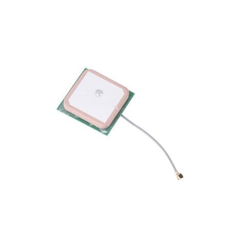
25x25x8mm 28dB High Gain GPS Antenna for NEO-6M/7M/8M
A ceramic active GPS antenna with 28 dB gain — upgrade for u-blox M6/M7/M8 GPS modules. Improves satellite lock time and fix quality, especially important for Loiter and Auto mode accuracy.
View on Zbotic
100A Multirotor ESC Power Distribution Battery Board For Quadcopter
A heavy-duty PDB that distributes battery power to all four ESCs. Built-in XT60 connector and solder pads make it easy to wire a Pixhawk-based quad cleanly and reliably.
View on ZboticFrequently Asked Questions
Both are open-source flight control stacks that run on Pixhawk hardware. ArduPilot (ArduCopter/Plane/Rover) has a larger community, more features for autonomous missions, and is generally considered more mature for multirotor applications. PX4 has a cleaner codebase and is preferred in the research/commercial space. Mission Planner is ArduPilot-specific; QGroundControl works with both.
Open Mission Planner and look at the pre-arm check messages in the HUD. Common causes: compass calibration failed, GPS not locked, accelerometer not calibrated, RC not calibrated, EKF unhealthy, or safety switch not pressed. Fix each listed error in turn.
ArduPilot’s default PIDs work adequately for most 450–550mm quad builds. However, for optimal performance, tuning is needed — especially for heavier platforms, unusual frame geometry, or powerful motors. Use Mission Planner’s AutoTune mode (arm, take off in AltHold, then switch to AutoTune) to let ArduPilot find optimal values automatically.
For beginners: the Holybro Pixhawk 4 Mini or any well-reviewed clone of the Pixhawk 2.4.8 (ensure it uses genuine ICM-20689 or MPU-6000 gyro). For professional builds: Cube Orange (best sensor isolation, dual IMU) or Holybro Pixhawk 6C. Avoid very cheap clones with counterfeit sensors — they produce noisy gyro data and make tuning a nightmare.
Yes — ArduCopter has dedicated spray controller support, terrain following, and boundary avoidance features used in agricultural drone builds. Large agricultural platforms using motors like the Hobbywing X6/X9 and EFT frames all typically run ArduPilot or DJI’s proprietary stack.
Conclusion
Configuring ArduPilot on a Pixhawk takes patience, but the process is methodical. Follow the steps in order — firmware, wiring, calibration, radio, modes, failsafe, motor test — and you will have a safe, capable platform ready for anything from backyard hovering to fully autonomous GPS missions.
The ArduPilot ecosystem’s documentation at ardupilot.org is exceptional — if you hit a problem not covered here, the parameter descriptions and community forums have answers for almost every scenario.
Need telemetry radios, vibration dampers, GPS antennas, or propellers for your Pixhawk build? Zbotic stocks genuine components with domestic shipping across India.
Shop Pixhawk & ArduPilot Components at Zbotic
Telemetry radios, vibration absorbers, GPS antennas, ESCs, propellers — everything for your Pixhawk build, shipped across India.
Browse Drone Components


Add comment