
Ever wondered how lie detectors work, or how wearable fitness bands detect stress? The answer lies in a fascinating piece of technology: the GSR (Galvanic Skin Response) sensor. This unassuming sensor measures the electrical conductance of your skin — a value that changes dramatically when you experience stress, excitement, fear, or any strong emotion. In this comprehensive guide, we’ll explore how GSR sensors work, how to wire one up with an Arduino, write code to read real-time data, and build projects ranging from a simple stress monitor to a lie detector prototype.
What is Galvanic Skin Response?
Galvanic Skin Response (GSR) — also called Electrodermal Activity (EDA) or Skin Conductance Response (SCR) — refers to the change in the electrical properties of the skin caused by sweat gland activity. When you experience an emotional or psychological stimulus, your autonomic nervous system activates sweat glands, particularly those in the fingertips and palms. This sweat changes the skin’s ability to conduct electricity.
The term “galvanic” comes from Luigi Galvani, the Italian physicist who pioneered the study of bioelectricity. GSR was first studied scientifically in the late 19th century and has since become a cornerstone measurement in:
- Psychophysiology — studying the relationship between psychological states and physiological responses
- Polygraph (lie detector) tests — measuring stress responses to questioning
- Biofeedback therapy — helping patients manage anxiety and stress
- Human-computer interaction — adaptive interfaces that respond to user stress
- Market research — measuring emotional responses to advertisements
The key insight is that GSR is largely involuntary — you cannot consciously control your sweat gland response the way you might control your breathing. This makes it a powerful indicator of genuine emotional states.
How Does a GSR Sensor Work?
A GSR sensor measures skin conductance — the inverse of skin resistance. Here’s the physics:
Skin Resistance: Dry skin has a relatively high electrical resistance (typically 20 kΩ to several MΩ). When sweat is produced by eccrine glands (predominantly in the palms and fingertips), the electrolytes in sweat (sodium, chloride, potassium) create a conductive path, dramatically lowering resistance to as little as 1–5 kΩ.
The Measurement Circuit: A GSR sensor passes a tiny, safe DC current (typically 0.5V or less) through two electrodes placed on the skin. The sensor measures the voltage drop across a known reference resistor to calculate the current flowing through the skin, from which it derives conductance (measured in microsiemens, μS) or resistance (in kΩ or MΩ).
Signal Components: The GSR signal has two main components:
- Tonic (Skin Conductance Level, SCL): The slow-changing baseline level, reflecting overall arousal state. This shifts over minutes to hours.
- Phasic (Skin Conductance Response, SCR): Rapid peaks (1–3 seconds) that occur in response to specific stimuli. Each significant emotional event produces a measurable spike.
For Arduino projects, you’ll primarily work with the raw ADC value which captures both components. With signal processing, you can separate the tonic and phasic components for more sophisticated analysis.
Types of GSR Sensors Available
Several GSR sensor modules are available for hobbyists and researchers:
1. Simple Resistive GSR Module
The most common type for Arduino projects. Features two electrode pads, a voltage divider circuit, and an analog output. Outputs a voltage proportional to skin conductance. Price: ₹200–500. Accuracy is modest but sufficient for educational projects.
2. Grove GSR Sensor (Seeed Studio)
A well-packaged module with finger clip electrodes and Grove connector. Works directly with Arduino analog pins. Good for beginners due to integrated amplification.
3. eHealth Shield
A professional-grade shield combining GSR with other biometric sensors (ECG, EMG, pulse oximetry). Designed for medical research prototyping. More expensive but highly accurate.
4. DIY GSR Circuit
For advanced users: build your own with two stainless steel or silver electrodes, a precision op-amp (LM358 or INA128), and a voltage divider. Allows full customization of the measurement range and bandwidth.
Wiring GSR Sensor to Arduino
For a standard GSR module with VCC, GND, and SIG pins:
GSR Sensor    →    Arduino Uno
-----------        -----------
VCC           →    5V
GND           →    GND
SIG           →    A0 (Analog Pin)
Electrode Placement: Attach the two electrode clips or pads to the index finger and middle finger of the same hand. Alternatively, place them on the fingertip and the first joint of the finger. Avoid bony areas — you want contact with the fleshy, high-sweat-gland areas of the fingertip pad.
Grounding Tip: Ensure the Arduino and any connected computer are properly grounded. Floating grounds can introduce significant noise into the GSR signal. If using a laptop on battery power, you’ll often get cleaner readings than when plugged in.
For the Grove GSR sensor, the wiring is even simpler — it connects directly to any Grove analog port on a compatible shield, with VCC, GND, and signal handled by the single connector.
Arduino Code for GSR Reading
Here’s a complete Arduino sketch to read, display, and log GSR data:
// GSR Sensor Basic Reading with Moving Average
// Connect SIG to A0, VCC to 5V, GND to GND

const int GSR_PIN = A0;
const int SAMPLE_WINDOW = 10;  // Moving average window size
int samples[10];
int sampleIndex = 0;
long sampleSum = 0;

void setup() {
  Serial.begin(115200);
  Serial.println("GSR Sensor Initialized");
  Serial.println("Time(ms),Raw,Smoothed,Resistance(kOhm)");

  // Pre-fill sample buffer
  for (int i = 0; i < SAMPLE_WINDOW; i++) {
    samples[i] = analogRead(GSR_PIN);
    sampleSum += samples[i];
    delay(10);
  }
}

void loop() {
  int rawValue = analogRead(GSR_PIN);

  // Update moving average
  sampleSum -= samples[sampleIndex];
  samples[sampleIndex] = rawValue;
  sampleSum += rawValue;
  sampleIndex = (sampleIndex + 1) % SAMPLE_WINDOW;

  int smoothed = sampleSum / SAMPLE_WINDOW;

  // Convert to resistance (approximate)
  // Assumes 1V reference divider with 56kOhm series resistor
  float voltage = smoothed * (5.0 / 1023.0);
  float resistance = (56000.0 * (5.0 - voltage)) / voltage;  // in Ohms
  float resistanceKOhm = resistance / 1000.0;

  // Print CSV for Serial Plotter
  Serial.print(millis());
  Serial.print(",");
  Serial.print(rawValue);
  Serial.print(",");
  Serial.print(smoothed);
  Serial.print(",");
  Serial.println(resistanceKOhm, 2);

  // Stress level detection (tune thresholds for your sensor)
  if (smoothed > 700) {
    Serial.println("STATUS: HIGH STRESS / HIGH AROUSAL");
  } else if (smoothed > 400) {
    Serial.println("STATUS: MODERATE AROUSAL");
  } else {
    Serial.println("STATUS: CALM / RELAXED");
  }

  delay(50);  // 20Hz sampling rate
}
Open the Arduino Serial Plotter (Tools → Serial Plotter) to see the GSR waveform in real-time. You’ll see the baseline drift slowly, with sharp spikes appearing whenever you experience a stimulus.
Advanced: Phasic/Tonic Decomposition
// Separate tonic (slow) from phasic (fast) components
// Tonic = very long moving average (slow changes)
// Phasic = raw signal minus tonic

const int TONIC_WINDOW = 200;  // ~10 seconds at 20Hz
long tonicBuffer[200];
long tonicSum = 0;
int tonicIndex = 0;

void computeComponents(int rawValue, float &tonic, float &phasic) {
  tonicSum -= tonicBuffer[tonicIndex];
  tonicBuffer[tonicIndex] = rawValue;
  tonicSum += rawValue;
  tonicIndex = (tonicIndex + 1) % TONIC_WINDOW;

  tonic = (float)tonicSum / TONIC_WINDOW;
  phasic = rawValue - tonic;
}
Calibration and Signal Processing
Raw GSR values vary enormously between individuals. Someone with naturally dry skin may read 50 on the ADC while someone with moist hands reads 800 — both being “normal” at rest. Effective calibration involves:
Baseline Establishment: Record 30–60 seconds of resting data before any test. Calculate the mean (μ) and standard deviation (σ) of this baseline. Use these to normalize subsequent readings: Normalized = (current – μ) / σ.
Sampling Rate: GSR responses peak 1–3 seconds after a stimulus. A sampling rate of 10–32 Hz is sufficient. Higher rates just add noise without adding information.
Electrode Contact Quality: Dry electrodes give noisy readings. Apply a tiny amount of isotonic saline gel (as used in ECG electrodes) for stable contact. Never use conductive gel intended for ultrasound — it has different conductivity.
Artifact Rejection: Movement artifacts (hand tremors, finger position changes) can cause large signal jumps that look like stress responses. If your ADC value changes more than 100 points in a single 50ms sample, flag it as a movement artifact and discard it.
Real-World Project Ideas
1. Stress Monitor Display
Combine the GSR sensor with an OLED display (SSD1306) and a buzzer. Show a real-time stress bar graph, and beep when the reading exceeds the calm baseline by more than 2 standard deviations. Perfect for a school science project or biofeedback wearable prototype.
2. Lie Detector Game
Wire up a GSR sensor, a green LED, a red LED, and a buzzer to an Arduino. Ask yes/no questions. If the phasic GSR spike exceeds a threshold within 3 seconds of the question, the red LED lights — indicating a stress response. Note: This is for entertainment only; real polygraphs are far more complex and unreliable even professionally.
3. Adaptive Music Player
Use an Arduino with Bluetooth module to send GSR data to a phone app. The app selects calming music when stress is high and energetic music when arousal is low. A creative project that combines biometrics with IoT.
4. Meditation Feedback System
Track SCL (tonic component) over a 10-minute meditation session. Log to an SD card. Visualize the data in Python (matplotlib) to see how effectively a meditation session reduced baseline arousal. This is a genuinely useful biofeedback tool.
5. Smart Home Stress Response
Using ESP8266/ESP32 + GSR, send stress readings via MQTT to Home Assistant. Automatically dim lights, lower thermostat, and start a relaxation playlist when stress is detected — a true wellness-oriented smart home system.
Medical and Research Applications
GSR sensing has moved well beyond hobbyist electronics into serious research and clinical domains:
Mental Health Monitoring: Wearables like Empatica E4 and Fitbit Sense use EDA to track stress levels continuously. Research shows that consistently elevated SCL correlates with chronic stress, anxiety disorders, and burnout. Long-term GSR monitoring can provide early warning of deteriorating mental health.
Autism Spectrum Research: Non-verbal individuals with ASD who cannot self-report emotional states show clear GSR responses to distressing stimuli. GSR devices help caregivers understand and respond to emotional states that would otherwise be invisible.
Neuromarketing: Advertisers measure GSR responses (alongside eye tracking and facial EMG) to evaluate emotional engagement with TV commercials, product packaging, and retail environments. A consumer might say they like an ad, but their GSR tells a different story.
Gaming and VR: Adaptive difficulty systems can use GSR to detect when a player is bored (flat, low GSR) or overwhelmed (high, spiking GSR) and adjust the game challenge accordingly.
Driver Monitoring: Automotive researchers study GSR to detect driver stress in heavy traffic, helping design safer car interiors and warning systems.
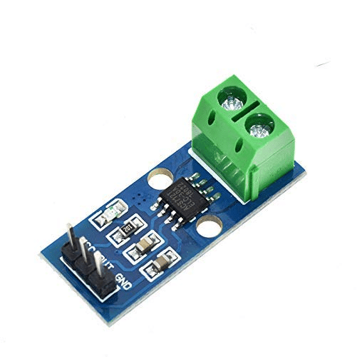
30A Range Current Sensor Module ACS712
Need to sense more than skin? The ACS712 is a precision current sensor for power monitoring in your Arduino projects — a great companion for any biometric sensor build.
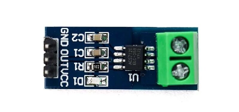
5A Range Current Sensor Module ACS712
The 5A ACS712 variant is ideal for low-power Arduino wearable projects where precise current sensing helps manage battery life alongside biometric measurements.
Troubleshooting Common Issues
Reading Stays Near Zero
Check electrode contact — dry skin or loose clips give near-zero conductance (high resistance). Wet your fingertips slightly or apply electrode gel. Verify VCC is at 5V and GND is connected.
Noisy, Erratic Readings
Electrical noise is the #1 issue with GSR. Solutions: (1) Add a 100nF capacitor between VCC and GND close to the module. (2) Use shielded cable for electrode leads. (3) Run on battery power to eliminate ground loops from USB. (4) Increase your moving average window to 20–50 samples.
Reading Saturates at Maximum
If the reading is pegged at 1023, your reference resistor is too small. The voltage divider is not designed for very conductive skin. Try swapping to a higher value series resistor (100 kΩ instead of 56 kΩ).
No Response to Stimuli
Electrodes must be on high-sweat-gland areas (fingertip pads, inner wrist). If placed on knuckles or forearms, you’ll see little response. Give the system 2–3 minutes to stabilize before testing — initial readings drift as the electrode-skin interface equilibrates.
Frequently Asked Questions
Is a GSR sensor safe to use?
Yes, completely. The voltage applied to the skin (typically 0.5V DC) is far below the threshold for any sensation or harm. The current is in the microampere range — thousands of times less than what you’d feel from static electricity. GSR sensors are used on infants in clinical research without any risk.
What is a normal GSR reading?
There is no universal “normal” — it varies by individual, time of day, temperature, and hydration. What matters is the relative change from each person’s own baseline. A typical resting skin conductance ranges from 1 to 20 μS (microsiemens), spiking to 20–30 μS under stress.
Can I use GSR to detect lies?
GSR can detect stress responses that often accompany deception, but it cannot definitively identify lying. Many honest people show high GSR due to nervousness, while practiced liars may show little response. Professional polygraph examiners use GSR as just one of several measurements (respiration, blood pressure) and extensive baseline protocols.
What is the difference between GSR and EDA?
They are the same phenomenon. EDA (Electrodermal Activity) is the broader scientific term covering all changes in the electrical properties of skin. GSR specifically refers to the galvanic (current-based) measurement method. SCR (Skin Conductance Response) refers to the phasic component of EDA. All three terms describe overlapping aspects of the same measurement.
Can I use aluminum foil as electrodes?
Technically yes, but the results will be very noisy. Aluminum oxidizes quickly, creating an uneven, high-resistance electrode-skin interface. Stainless steel, silver, or gold-plated electrodes are far superior. For quick tests, copper PCB pads or stainless steel bolts work acceptably.
Does the GSR sensor work with ESP32?
Yes. The ESP32’s ADC is 12-bit (0–4095) compared to the Arduino Uno’s 10-bit (0–1023). You’ll need to adjust your thresholds accordingly (multiply by 4). Note that the ESP32’s ADC has some non-linearity above 3.1V — use an external ADC (ADS1115) for research-grade accuracy.
Conclusion
The GSR sensor is one of the most fascinating biometric sensors available to makers and researchers. It bridges the gap between electronics and human psychology, offering a real-time window into the autonomic nervous system. Whether you’re building a simple stress light for your desk, a lie detector game for a science fair, or contributing to genuine wellness technology, the GSR sensor delivers remarkable insights for a very modest investment.
The key to success is patient calibration, clean electrode contact, and thoughtful signal processing. Start with the basic sketch above, watch the Serial Plotter as you think stressful thoughts or watch a scary movie, and you’ll be hooked. From there, the applications are limited only by your creativity.


Add comment