
One of the most underused yet most powerful features of the ESP32 is its ULP (Ultra-Low-Power) coprocessor. This tiny processor can run independently while the main dual-core CPU is in deep sleep, consuming only a fraction of the power. In this ESP32 ULP coprocessor tutorial, we’ll explore what the ULP is, why it’s game-changing for battery-powered IoT projects, and how to write and run ULP programs to read sensors and wake the main CPU only when necessary.
What is the ESP32 ULP Coprocessor?
The ULP coprocessor is a small, low-power processor built into the ESP32’s power management unit (PMU). Unlike the main Xtensa dual-core CPU, which requires substantial power to operate, the ULP is designed to perform simple, repetitive tasks at extremely low current draw.
Key characteristics of the ULP:
- Operates from the RTC power domain — remains active even when the main CPU is in deep sleep
- Has access to RTC slow memory (8KB on original ESP32, 4KB on ESP32-S2/S3)
- Can access RTC GPIOs, the built-in ADC (for analog sensor readings), and I2C (on newer chips)
- Runs at a low frequency (typically 8-150 kHz depending on configuration)
- Can wake the main CPU by setting a wakeup flag in RTC memory
The practical benefit is enormous: instead of waking the full ESP32 (which draws 100-240mA) every 5 minutes to read a temperature sensor, the ULP can read the sensor every minute while the main CPU stays asleep, and only trigger a full wake when a threshold is crossed or data needs to be transmitted. Battery life can go from days to months.
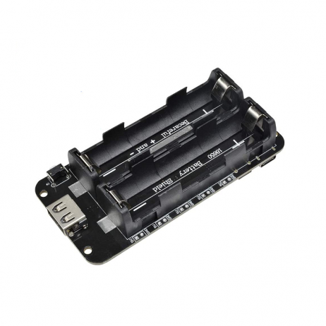
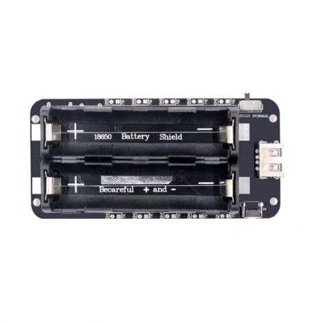
2 x 18650 Lithium Battery Shield for ESP32/ESP8266
Power your ULP-based ESP32 project for weeks or months with this dual 18650 battery shield — includes USB charging and 5V/3.3V regulated output.
Power Consumption: ULP vs Active Mode
To appreciate the ULP, consider these typical current figures for the ESP32:
| Mode | Current Draw | Battery Life (2000mAh) |
|---|---|---|
| Active (Wi-Fi TX) | 240 mA (peak) | ~8 hours |
| Active (CPU only) | ~80 mA | ~25 hours |
| Light Sleep | ~0.8 mA | ~104 days |
| Deep Sleep | ~10–150 µA | ~1–3 years |
| ULP Active (main CPU sleeping) | ~1.5–5 µA (ULP core only) | Very long |
In a real-world sensor node that wakes the main CPU every 10 minutes to transmit data over Wi-Fi (2 seconds each time), average current with ULP-driven sensing can be well under 1mA — giving over 80 days on a single 2000mAh cell.
ULP Variants: FSM vs RISC-V
Espressif has two types of ULP coprocessors across their chip family:
ULP-FSM (Finite State Machine)
Found on the original ESP32, ESP32-S2, and ESP32-S3. This is programmed in a custom assembly language. It supports:
- Basic arithmetic (ADD, SUB)
- Memory read/write (to RTC slow memory)
- ADC sampling
- I2C communication (on ESP32-S2/S3 only)
- GPIO control
- Setting wakeup conditions for the main CPU
The FSM ULP is powerful but requires writing assembly code, which has a learning curve.
ULP-RISC-V
Found on ESP32-S2, ESP32-S3, ESP32-C6, and newer chips. This is a real RISC-V processor that can be programmed in C — much more accessible for most developers. Espressif provides a specific ULP RISC-V C toolchain as part of ESP-IDF.
For this tutorial, we’ll demonstrate both, starting with ULP-FSM on the classic ESP32.
Programming the ULP with ESP-IDF
The ULP is not supported in the standard Arduino IDE. You must use ESP-IDF or PlatformIO with ESP-IDF framework.
ULP-FSM Example: Toggle GPIO Every 1 Second
ULP assembly files have the .S extension and use special macros from the ulp_macros.h header:
/* ulp_gpio_toggle.S */
#include "soc/rtc_cntl_reg.h"
#include "soc/rtc_io_reg.h"
#include "soc/soc_ulp.h"

.global entry
entry:
    /* Read GPIO state and toggle */
    READ_RTC_REG(RTC_GPIO_OUT_REG, RTC_GPIO_OUT_DATA_S + 2, 1)
    /* result in r0 */
    JUMPR toggle_off, 1, EQ

toggle_on:
    WRITE_RTC_REG(RTC_GPIO_OUT_REG, RTC_GPIO_OUT_DATA_S + 2, 1, 1)
    JUMP end

toggle_off:
    WRITE_RTC_REG(RTC_GPIO_OUT_REG, RTC_GPIO_OUT_DATA_S + 2, 1, 0)

end:
    HALT  /* ULP halts; woken again by timer */
In your main application, load and run the ULP program:
#include "ulp.h"
#include "esp_sleep.h"
#include "soc/rtc_cntl_reg.h"
#include "driver/rtc_io.h"

extern const uint8_t ulp_main_bin_start[] asm("_binary_ulp_gpio_toggle_bin_start");
extern const uint8_t ulp_main_bin_end[]   asm("_binary_ulp_gpio_toggle_bin_end");

void app_main() {
    // Configure RTC GPIO 2
    rtc_gpio_init(GPIO_NUM_2);
    rtc_gpio_set_direction(GPIO_NUM_2, RTC_GPIO_MODE_OUTPUT_ONLY);

    // Load ULP program
    ulp_load_binary(0, ulp_main_bin_start,
        (ulp_main_bin_end - ulp_main_bin_start) / sizeof(uint32_t));

    // Set ULP timer to wake every 1000ms
    ulp_set_wakeup_period(0, 1000 * 1000); // microseconds

    // Start ULP
    ulp_run(&ulp_entry - RTC_SLOW_MEM);

    // Put main CPU to deep sleep; ULP stays active
    esp_deep_sleep_start();
}
Project: ULP Reads Temperature Sensor and Wakes CPU
Here’s a practical project: using the ULP-RISC-V (on ESP32-S3) to periodically read an LM35 temperature sensor via ADC and wake the main CPU only if temperature exceeds a threshold.
Hardware Setup
- LM35 temperature sensor: output connected to GPIO1 (an RTC-capable ADC pin)
- VCC to 3.3V, GND to GND

LM35 Temperature Sensor
A precision analog temperature sensor that outputs 10mV/°C — perfect for ADC-based ULP temperature monitoring projects without I2C overhead.
ULP RISC-V Code (C)
/* ulp/main.c — runs on ULP RISC-V */
#include "ulp_riscv.h"
#include "ulp_riscv_utils.h"
#include "ulp_riscv_adc.h"

#define TEMP_THRESHOLD_ADC 2400  /* ~35°C for LM35 at 12-bit ADC */

volatile int32_t ulp_adc_value;

int main() {
    ulp_adc_value = ulp_riscv_adc_read_channel(ADC_UNIT_1, ADC_CHANNEL_0);

    if (ulp_adc_value > TEMP_THRESHOLD_ADC) {
        /* Wake main CPU */
        ulp_riscv_wakeup_main_processor();
    }
    return 0; /* ULP halts and is restarted by timer */
}
In the main application, read ulp_adc_value from RTC slow memory on wakeup to get the last ADC reading, convert it to temperature (°C = ADC_count × 3300 / 4095 / 10), and proceed with Wi-Fi transmission.
18650 Battery Shield V8 for ESP32 — 5V/3A Output
A higher-current V8 battery shield delivering 5V/3A — handles the Wi-Fi burst current when your ULP wakes the main ESP32 CPU for data transmission.
Battery Life Tips for ULP-Based Projects
Getting the most battery life from a ULP-based design requires careful attention to several factors beyond just the code:
- Power the sensor from a GPIO: Drive the LM35 or DHT11 from a GPIO pin and set it HIGH only when the ULP needs to take a reading. Leaving sensors powered continuously wastes current even in sleep mode.
- Use an RTC-domain GPIO for the sensor power rail: RTC GPIOs remain controllable during deep sleep, so the ULP can power the sensor on, wait for stabilisation, read, and then power it off again.
- Increase the ULP wake interval: The less frequently the ULP runs, the lower the average current. For non-critical monitoring (soil moisture, ambient temperature), once every 60 seconds is usually sufficient.
- Minimise main CPU wake time: Once the main CPU wakes, perform only the necessary tasks (transmit data, update RTC variables) and go back to sleep as fast as possible. Disable Wi-Fi before calling
esp_deep_sleep_start(). - Use LDO with low quiescent current: On custom PCBs, choose a voltage regulator with <1µA quiescent current to avoid it dominating the sleep power budget.
Frequently Asked Questions
Does the ULP work with the Arduino IDE?
Not directly. The Arduino core for ESP32 does not expose ULP programming tools. You must use ESP-IDF (via the command line or within PlatformIO). Some community projects provide ULP helpers for Arduino, but they are limited and not officially supported.
Can the ULP access Wi-Fi or Bluetooth?
No. The ULP only has access to the RTC power domain — it cannot activate the Wi-Fi/Bluetooth radio. Its role is to handle periodic sensing with minimal power and wake the main CPU when the radio is needed.
What is RTC slow memory and how much is available?
RTC slow memory is a special SRAM region that retains its contents during deep sleep. On the original ESP32, there is 8KB available (shared between ULP program storage and data). On ESP32-S2/S3, there is 4–8KB. Variables shared between ULP and main CPU are placed in this region using the RTC_SLOW_ATTR attribute.
Can I run multiple ULP programs simultaneously?
No. The ULP has a single program counter and executes one program sequentially. However, your ULP code can implement a simple state machine to handle multiple tasks (reading different sensors, checking different conditions) within a single program run.
Which ESP32 variant has the best ULP support?
The ESP32-S3 has the most capable ULP implementation, combining both the FSM and RISC-V coprocessors with support for I2C communication from the ULP. For most projects, the classic ESP32 with ULP-FSM is sufficient. The ESP32-C3 and C6 use ULP-RISC-V and are ideal when C programming is preferred.
Power Your Next Battery IoT Project
Get ESP32 development boards, sensors, and battery shields for your ultra-low-power IoT project at Zbotic.in — India’s go-to store for electronics components with pan-India delivery.


Add comment