
Table of Contents
- Why Use ESP32 for Servo Control?
- Servo Motor Basics: PWM and Angles
- ESP32 LEDC PWM API Explained
- Wiring a Single Servo to ESP32
- Code: Single Servo Control
- Controlling Multiple Servos Simultaneously
- Smooth Motion: Interpolation and Easing
- Wi-Fi Web Interface for Remote Servo Control
- Power Supply and Current Considerations
- SG90 vs MG90 vs MG996: Choosing the Right Servo
- Recommended Products
- Frequently Asked Questions
- Conclusion
Why Use ESP32 for Servo Control?
The ESP32 microcontroller has become the preferred platform for servo control projects that go beyond simple position commands. Here is why makers and engineers choose ESP32 over Arduino Uno for servo applications:
- 16 independent hardware PWM channels (LEDC): The ESP32’s LED Control (LEDC) peripheral generates up to 16 hardware-accurate PWM signals simultaneously. Unlike Arduino’s timer-based approach that shares timers between pins, each ESP32 LEDC channel runs independently, enabling truly simultaneous multi-servo control with precise timing.
- Higher PWM resolution: Up to 16-bit resolution (65,535 steps) vs. Arduino’s 8-bit (255 steps). This translates to much finer angular positioning — approximately 0.003° per step vs. Arduino’s 0.7° per step.
- Wi-Fi and Bluetooth built-in: Control servos remotely via web browser, smartphone app, or MQTT without any additional hardware modules.
- Dual-core processing: Run servo motion on one core and Wi-Fi/Bluetooth on the other, eliminating latency conflicts.
- 3.3V logic: Note — standard servo signal lines work with 3.3 V logic (the PWM signal), though servo power requires 5 V (or higher for MG996-class servos).
Servo Motor Basics: PWM and Angles
A standard hobby servo expects a PWM signal with these parameters:
- Frequency: 50 Hz (one pulse every 20 ms)
- Pulse width at 0°: ~500–600 µs
- Pulse width at 90°: ~1,500 µs (centre position)
- Pulse width at 180°: ~2,400–2,500 µs
The servo’s internal circuit compares the received pulse width to its current shaft position (measured by a potentiometer) and drives a small DC motor to reduce the error to zero. The result is a closed-loop position control system in a compact package.
Important: Pulse width ranges vary between servo brands and models. The SG90, for example, has a usable range of approximately 500–2,400 µs. Sending pulses outside this range will drive the servo into its mechanical stop, causing buzzing and heat buildup. Always test with conservative ranges (600–2,400 µs) first and expand if needed.
For continuous rotation servos (modified for robotics drive wheels), the 1,500 µs pulse is the stop position, below 1,500 µs rotates one direction, and above 1,500 µs rotates the other direction.
ESP32 LEDC PWM API Explained
The ESP32 Arduino Core provides the LEDC (LED Control) API for PWM generation. For servo control, you work with three key functions:
ledcSetup(channel, frequency, resolution_bits)— Configure a LEDC channelledcAttachPin(pin, channel)— Attach a GPIO pin to a LEDC channelledcWrite(channel, duty)— Set the duty cycle (0 to 2^resolution – 1)
For servo control at 50 Hz with 16-bit resolution:
- Period = 1/50 Hz = 20 ms = 20,000 µs
- Total steps at 16-bit = 65,535
- Each µs = 65,535 / 20,000 = 3.28 steps
- To set 1,500 µs: duty = 1500 × 3.28 = 4,915
This gives you positioning resolution of approximately 1/3.28 µs = 0.3 µs per step — far finer than any hobby servo can physically resolve, but useful when combining multiple servo motions programmatically.
Note for ESP32 Arduino Core v3.x users: The API changed significantly. In v3.x, use ledcAttach(pin, frequency, resolution) and ledcWrite(pin, duty) instead of the separate setup/attach functions. Check your ESP32 core version with ESP.getSdkVersion().
Wiring a Single Servo to ESP32
Hobby servos have a 3-wire connector:
- Brown/Black wire: GND
- Red wire: Power (5 V for SG90, 6 V for MG996)
- Orange/Yellow/White wire: Signal (PWM input)
Wiring to ESP32 DevKit:
| Servo Wire | Connect To | Notes |
|---|---|---|
| Brown/Black (GND) | ESP32 GND + Power supply GND | Common ground is critical |
| Red (Power) | External 5V supply (NOT ESP32 5V pin) | Servos draw up to 1A — don’t power from ESP32 |
| Orange/Yellow (Signal) | ESP32 GPIO (e.g., GPIO 13) | Any GPIO except 6, 7, 8, 9, 10, 11 (flash) |
Critical wiring note: Never power multiple servos from the ESP32’s onboard 5 V pin or 3.3 V regulator. Even one SG90 can draw 250 mA stall current, which will exceed the ESP32 devboard’s onboard regulator limit and crash the microcontroller. Use a dedicated 5 V supply (phone charger, buck converter, or USB power bank) with its GND connected to ESP32 GND.
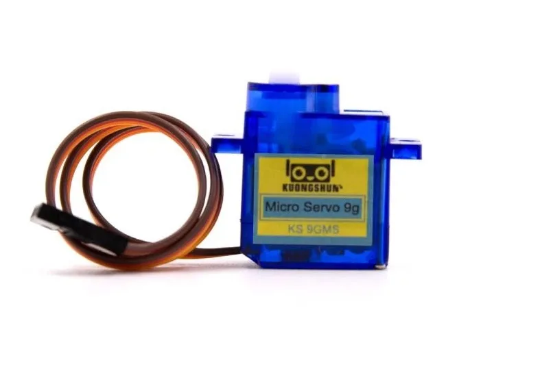
Servo SG90 9g 180 Degree
The classic 9g micro servo — ultra-light, 180° range, and compatible with any ESP32 GPIO. Perfect for robotics, pan-tilt mechanisms, and automation prototypes.
Code: Single Servo Control
Complete ESP32 sketch for a single servo with degree-based positioning:
// ESP32 Servo Control using LEDC
// Compatible with ESP32 Arduino Core v2.x

#define SERVO_PIN  13
#define LEDC_CHAN  0
#define LEDC_FREQ  50       // 50 Hz for servo
#define LEDC_RES   16       // 16-bit resolution

// Pulse width in microseconds
#define SERVO_MIN_US  500
#define SERVO_MAX_US  2400

void setup() {
  ledcSetup(LEDC_CHAN, LEDC_FREQ, LEDC_RES);
  ledcAttachPin(SERVO_PIN, LEDC_CHAN);
  Serial.begin(115200);
  Serial.println("ESP32 Servo Control");
  setServoDeg(90); // Centre position on startup
  delay(1000);
}

// Convert microseconds to LEDC duty
uint32_t usToDuty(int us) {
  return (uint32_t)(us * 65535.0 / 20000.0);
}

// Set servo position by angle (0-180 degrees)
void setServoDeg(int deg) {
  deg = constrain(deg, 0, 180);
  int us = map(deg, 0, 180, SERVO_MIN_US, SERVO_MAX_US);
  ledcWrite(LEDC_CHAN, usToDuty(us));
}

void loop() {
  // Sweep 0 to 180 and back
  for (int pos = 0; pos = 0; pos -= 5) {
    setServoDeg(pos);
    delay(50);
  }
  delay(500);
}
Controlling Multiple Servos Simultaneously
ESP32 can control up to 16 servos simultaneously using 16 independent LEDC channels. Here is a clean object-oriented approach:
// Multi-servo control on ESP32
// Supports up to 16 servos

struct Servo {
  int pin;
  int channel;
  int minUs;
  int maxUs;
  int currentDeg;
};

// Define your servos
Servo servos[] = {
  {13, 0, 500, 2400, 90},  // Servo 0: GPIO13, Channel 0
  {12, 1, 500, 2400, 90},  // Servo 1: GPIO12, Channel 1
  {14, 2, 600, 2300, 90},  // Servo 2: GPIO14, Channel 2
  {27, 3, 500, 2400, 90},  // Servo 3: GPIO27, Channel 3
};

const int NUM_SERVOS = 4;

void initServos() {
  for (int i = 0; i < NUM_SERVOS; i++) {
    ledcSetup(servos[i].channel, 50, 16);
    ledcAttachPin(servos[i].pin, servos[i].channel);
    setServoDeg(i, 90); // All to centre
  }
}

uint32_t usToDuty(int us) {
  return (uint32_t)(us * 65535.0 / 20000.0);
}

void setServoDeg(int idx, int deg) {
  deg = constrain(deg, 0, 180);
  servos[idx].currentDeg = deg;
  int us = map(deg, 0, 180, servos[idx].minUs, servos[idx].maxUs);
  ledcWrite(servos[idx].channel, usToDuty(us));
}

void setup() {
  Serial.begin(115200);
  initServos();
  delay(1000);
}

void loop() {
  // Wave: each servo offsets by 45 degrees in phase
  unsigned long t = millis();
  for (int i = 0; i < NUM_SERVOS; i++) {
    float phase = (float)i * 45.0;
    int deg = 90 + (int)(80.0 * sin((t / 1000.0) * 2 * PI + phase * PI / 180.0));
    setServoDeg(i, deg);
  }
  delay(20); // 50 Hz update rate
}
This code makes four servos perform a smooth wave motion with each servo 45° out of phase — useful for animatronic tentacles, robotic fingers, and hexapod leg segments.

TowerPro SG90 180 Degree Rotation Servo Motor
Industry-standard TowerPro SG90 — precise, durable, and widely tested with ESP32. Ideal for 4-servo wave arrays, pan-tilt systems, and robotic grippers.
Smooth Motion: Interpolation and Easing
Jumping a servo directly from 0° to 180° causes mechanical shock, noise, and stress on the gears. Smooth motion requires interpolation — moving the servo through intermediate positions over time.
Linear Interpolation (Lerp)
void sweepTo(int idx, int targetDeg, int stepDelayMs) {
  int startDeg = servos[idx].currentDeg;
  int steps = abs(targetDeg - startDeg);
  for (int i = 0; i  startDeg ? i : -i);
    setServoDeg(idx, deg);
    delay(stepDelayMs);
  }
}
Ease-In-Out (Sinusoidal)
void easeServeTo(int idx, int targetDeg, int durationMs) {
  int startDeg = servos[idx].currentDeg;
  int steps = durationMs / 20; // 50 Hz update
  for (int i = 0; i <= steps; i++) {
    // Sinusoidal ease-in-out
    float t = (float)i / steps;
    float ease = 0.5 - 0.5 * cos(t * PI);
    int deg = startDeg + (int)((targetDeg - startDeg) * ease);
    setServoDeg(idx, deg);
    delay(20);
  }
}
The sinusoidal ease creates a natural deceleration at the target position, eliminating the bounce and stress that linear sweeps create. Call it like: easeServeTo(0, 45, 800); to move servo 0 to 45° over 800 ms with smooth acceleration and deceleration.
Wi-Fi Web Interface for Remote Servo Control
One of ESP32’s killer features for servo projects is built-in Wi-Fi. Here’s a minimal web server that lets you control servo angle from any browser on the same network:
#include <WiFi.h>
#include <WebServer.h>

const char* ssid = "YourWiFi";
const char* password = "YourPassword";

WebServer server(80);

void handleRoot() {
  String html = "<html><body>";
  html += "<h2>ESP32 Servo Control</h2>";
  html += "<input type='range' min='0' max='180' value='90' ";
  html += "oninput="fetch('/set?deg=' + this.value)" style='width:300px'>";
  html += "</body></html>";
  server.send(200, "text/html", html);
}

void handleSet() {
  if (server.hasArg("deg")) {
    int deg = server.arg("deg").toInt();
    setServoDeg(0, deg);
    server.send(200, "text/plain", "OK");
  }
}

void setup() {
  // ... servo init ...
  WiFi.begin(ssid, password);
  while (WiFi.status() != WL_CONNECTED) delay(500);
  Serial.println(WiFi.localIP());
  server.on("/", handleRoot);
  server.on("/set", handleSet);
  server.begin();
}

void loop() {
  server.handleClient();
}
Open the ESP32’s IP address in a browser to see a slider that controls the servo in real time from anywhere on your Wi-Fi network.

Servo MG996 13KG 180 Degree High Quality
Heavy-duty metal-geared servo with 13 kg-cm torque — the go-to choice for ESP32 robotic arms, steering mechanisms, and high-load multi-servo systems.
Power Supply and Current Considerations
Power is the most commonly overlooked aspect of multi-servo projects:
- SG90 at stall: ~700 mA per servo
- MG996 at stall: ~2,500 mA per servo
- Rule of thumb: For N servos, your supply should deliver at least N × stall_current × 0.5 (practical average)
For 4 SG90 servos: 4 × 700 mA × 0.5 = 1.4 A minimum supply. Use a 3 A supply for headroom.
Use a dedicated 5V regulated supply (not the ESP32’s USB power) and connect the supply GND directly to ESP32 GND. Add 100–470 µF electrolytic capacitors across the servo power rail to absorb current transients when servos start moving.
SG90 vs MG90 vs MG996: Choosing the Right Servo
| Servo | Torque | Weight | Gears | Best For |
|---|---|---|---|---|
| SG90 | 1.8 kg-cm | 9 g | Plastic | Light payloads, rapid prototyping |
| MG90S | 2.2 kg-cm | 13 g | Metal | Higher loads, longer life |
| MG996 | 13 kg-cm | 55 g | Metal | Robotic arms, heavy steering |
Recommended Products
Build your ESP32 multi-servo project with these components from Zbotic:

Servo MG996 13KG 180 Degree
Metal-geared 13 kg-cm servo at a budget price — ideal for ESP32 robotic arm builds and steering mechanisms where SG90 torque isn’t sufficient.

Servo Mount Holder Bracket for SG90/MG90 (Pack of 2)
Plastic mounting brackets for SG90 and MG90 servos — makes it easy to mechanically mount servos at precise angles in your multi-servo ESP32 frame.

Aluminum Servo Horn/Arm 25T Round Type Disc MG995 MG996
Metal servo horn disc for MG996 servos — much stronger than plastic horns for load-bearing robotic arm joints driven by your ESP32 system.
Frequently Asked Questions
Can I use the Arduino Servo library on ESP32?
Yes. The ESP32 Arduino Core includes a Servo.h library that wraps the LEDC peripheral. However, it only supports up to 12 servos per core (limited by available LEDC channels after other peripherals). The direct LEDC API shown in this guide gives you more control and is preferred for professional projects.
Why does my ESP32 reset when servos start moving?
The ESP32 is drawing too much power. Servo startup current spikes cause the 3.3 V or 5 V rail to sag below the ESP32’s minimum operating voltage, triggering a brownout reset. Add a 470 µF–1,000 µF capacitor across the servo 5 V power rail and ensure your power supply is rated for adequate current.
How many servos can I control with one ESP32?
The LEDC hardware supports 16 channels (8 high-speed + 8 low-speed timers), so technically 16 servos. Practically, power limits the number: at 5 V with a 5 A supply, you can drive approximately 7 SG90 servos at moderate load. For more servos, use a PCA9685 16-channel I2C servo driver board which offloads PWM generation to dedicated hardware and supports virtually unlimited cascading.
What GPIO pins are safe to use for servo signals on ESP32?
Avoid GPIO 6–11 (used for internal flash). GPIO 34, 35, 36, 39 are input-only. Best servo signal pins: GPIO 12, 13, 14, 15, 16, 17, 18, 19, 21, 22, 23, 25, 26, 27. Note that GPIO 12 affects boot mode if pulled high — safer to use GPIO 13, 14, or higher for the first servo to avoid boot issues.
Does the servo jitter when ESP32 is doing Wi-Fi operations?
With the direct LEDC API, servo jitter during Wi-Fi is minimal because LEDC generates PWM in hardware independently of the CPU. Unlike software PWM (used by some libraries), hardware LEDC continues generating precise pulses even when the CPU is handling Wi-Fi interrupts. For sensitive applications, assign servo updates to Core 0 and Wi-Fi to Core 1 using FreeRTOS tasks.
Conclusion
ESP32 is an exceptional platform for multi-servo projects thanks to its 16 hardware PWM channels, high PWM resolution, and built-in Wi-Fi for remote control. The LEDC API gives you direct, precise control that surpasses Arduino’s timer-based approach, and the dual-core architecture eliminates conflicts between servo motion and wireless communication.
Start with a single SG90 and the basic sketch, then expand to multiple servos with the struct-based multi-servo code. Add smooth easing interpolation for professional-quality motion, and integrate the Wi-Fi web server for remote control via any browser.
Find the right servos, mounting hardware, and extension cables for your ESP32 project in Zbotic’s motors and actuators collection.


One comment
David De la Haye
This is a very useful and complete explanation, thank you.
However, are you aware that this may be impacted by recent migration?
https://docs.espressif.com/projects/arduino-esp32/en/latest/migration_guides/2.x_to_3.0.html