
One of the most powerful features of the I2C protocol is the ability to connect multiple sensors to a single ESP32 using the I2C bus — sharing just two wires (SDA and SCL) for all devices. Whether you need to scan and read I2C addresses, connect a BME280 weather sensor alongside an OLED display and an MPU6050 accelerometer, or debug why your sensor is not responding, this comprehensive guide will teach you everything you need to know about working with multiple I2C sensors on the ESP32. This tutorial is designed for Indian makers who want to build professional multi-sensor IoT projects with minimal wiring complexity.
I2C Protocol Basics for ESP32
I2C (Inter-Integrated Circuit) is a two-wire serial communication protocol invented by Philips in 1982. It uses just two lines:
- SDA (Serial Data Line): Carries data bidirectionally between master and slave.
- SCL (Serial Clock Line): Provides the synchronisation clock generated by the master (ESP32).
Both lines require pull-up resistors to the supply voltage (typically 4.7kΩ to 3.3V). Most breakout modules for ESP32 include onboard pull-ups, but when connecting multiple devices you may need to reduce the pull-up resistance to maintain signal integrity.
I2C Addressing
Each I2C device has a unique 7-bit address (range: 0x00 to 0x7F). The address is either fixed by the manufacturer or partially configurable via address pins (ADDR pins) on the module. A single I2C bus can theoretically support up to 127 devices, though in practice 10-15 is a realistic limit due to capacitance constraints.
Common I2C Sensor Addresses
| Sensor/Module | Default I2C Address | Alternate Address |
|---|---|---|
| BME280 / BMP280 | 0x76 | 0x77 (SDO → VCC) |
| SSD1306 OLED Display | 0x3C | 0x3D (address pin) |
| MPU6050 IMU | 0x68 | 0x69 (AD0 → VCC) |
| ADS1115 ADC | 0x48 | 0x49, 0x4A, 0x4B |
| DS3231 RTC | 0x68 | Fixed (same as MPU6050!) |
| PCF8574 I2C GPIO Expander | 0x20 | 0x20-0x27 (A0-A2 pins) |
| HTU21D Humidity | 0x40 | Fixed |
| INA219 Current Sensor | 0x40 | 0x41, 0x44, 0x45 |
ESP32 I2C Pins and Configuration
One of the great advantages of the ESP32 is that I2C can be assigned to virtually any GPIO pins using the Arduino Wire library. By default, the ESP32 Arduino core uses:
- SDA: GPIO21
- SCL: GPIO22
However, you can reassign these to any other GPIO pins, and the ESP32 actually has two hardware I2C controllers (I2C0 and I2C1), allowing two independent I2C buses simultaneously.
Default I2C Initialization
#include <Wire.h>

void setup() {
  // Default pins (GPIO21=SDA, GPIO22=SCL)
  Wire.begin();

  // OR specify custom pins:
  Wire.begin(21, 22); // SDA, SCL

  // Set custom clock speed (default 100kHz, up to 400kHz for fast mode)
  Wire.setClock(400000); // 400kHz Fast Mode
}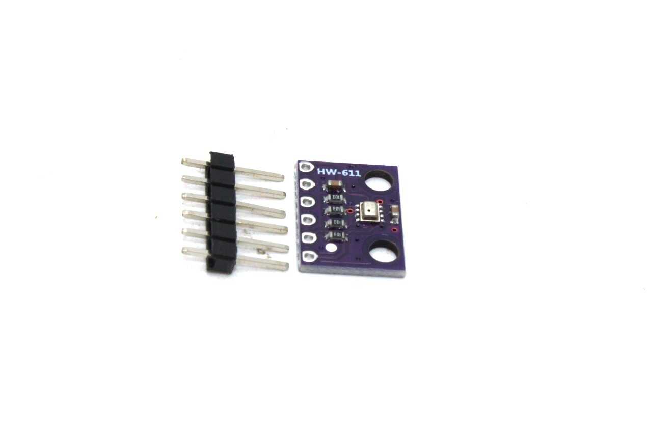
BMP280 Barometric Pressure and Altitude Sensor I2C/SPI Module
The BMP280 is one of the most popular I2C sensors for ESP32 — pairs perfectly with other I2C sensors like the OLED display and MPU6050 on a shared bus.
I2C Scanner: Finding Device Addresses
Before writing any sensor code, always run the I2C scanner sketch first. This is the single most useful debugging tool for I2C projects. It scans all 127 possible I2C addresses and reports which ones respond.
I2C Scanner Sketch for ESP32
#include <Wire.h>

void setup() {
  Serial.begin(115200);
  Wire.begin(21, 22); // SDA, SCL

  Serial.println("nI2C Scanner starting...");
  Serial.println("Scanning for I2C devices...");
}

void loop() {
  int devicesFound = 0;

  for (uint8_t address = 1; address < 127; address++) {
    Wire.beginTransmission(address);
    uint8_t error = Wire.endTransmission();

    if (error == 0) {
      Serial.printf("I2C device found at address 0x%02Xn", address);
      devicesFound++;
    } else if (error == 4) {
      Serial.printf("Unknown error at address 0x%02Xn", address);
    }
  }

  if (devicesFound == 0) {
    Serial.println("No I2C devices found!");
    Serial.println("Check your wiring — SDA and SCL connections.");
  } else {
    Serial.printf("Scan complete. %d device(s) found.n", devicesFound);
  }

  Serial.println("---");
  delay(5000); // Scan every 5 seconds
}
Understanding Scanner Results
When you run this on an ESP32 with a BME280 and SSD1306 OLED connected, you should see:
I2C Scanner starting...
Scanning for I2C devices...
I2C device found at address 0x3C    <-- SSD1306 OLED
I2C device found at address 0x76    <-- BME280
Scan complete. 2 device(s) found.
---
If no devices are found, check: power supply, SDA/SCL connections, pull-up resistors, and whether the sensor needs an initial settling time after power-on.
Connecting and Reading Multiple I2C Sensors
Once you have confirmed addresses with the scanner, here is a complete example reading data from three I2C sensors simultaneously: BME280 (temperature/humidity/pressure), SSD1306 OLED display, and an MPU6050 accelerometer/gyroscope.
Wiring Multiple I2C Sensors
All sensors share the same two wires:
- Connect all SDA pins together to ESP32 GPIO21
- Connect all SCL pins together to ESP32 GPIO22
- Connect all VCC pins to ESP32 3.3V (or 5V if the module requires it)
- Connect all GND pins to ESP32 GND
Complete Multi-Sensor Example
#include <Wire.h>
#include <Adafruit_BME280.h>
#include <Adafruit_SSD1306.h>
#include <MPU6050.h>

#define SCREEN_WIDTH 128
#define SCREEN_HEIGHT 64
#define OLED_ADDR 0x3C

Adafruit_BME280 bme;
Adafruit_SSD1306 display(SCREEN_WIDTH, SCREEN_HEIGHT, &Wire, -1);
MPU6050 mpu;

void setup() {
  Serial.begin(115200);
  Wire.begin(21, 22); // ESP32 default I2C pins
  Wire.setClock(400000); // 400kHz for better performance

  // Init BME280
  if (!bme.begin(0x76)) {
    Serial.println("BME280 not found! Check address (0x76 or 0x77)");
  } else {
    Serial.println("BME280 initialized OK");
  }

  // Init OLED
  if (!display.begin(SSD1306_SWITCHCAPVCC, OLED_ADDR)) {
    Serial.println("SSD1306 OLED not found!");
  } else {
    Serial.println("OLED initialized OK");
    display.clearDisplay();
    display.setTextSize(1);
    display.setTextColor(WHITE);
    display.setCursor(0, 0);
    display.println("ESP32 I2C Multi-Sensor");
    display.display();
  }

  // Init MPU6050
  mpu.initialize();
  if (mpu.testConnection()) {
    Serial.println("MPU6050 initialized OK");
  } else {
    Serial.println("MPU6050 not found! Check address (0x68 or 0x69)");
  }
}

void loop() {
  // Read BME280
  float temperature = bme.readTemperature();
  float humidity    = bme.readHumidity();
  float pressure    = bme.readPressure() / 100.0F;

  // Read MPU6050
  int16_t ax, ay, az, gx, gy, gz;
  mpu.getMotion6(&ax, &ay, &az, &gx, &gy, &gz);

  // Convert to g (assuming ±2g range, sensitivity 16384 LSB/g)
  float accel_x = ax / 16384.0;
  float accel_y = ay / 16384.0;
  float accel_z = az / 16384.0;

  // Print to Serial
  Serial.printf("Temp: %.1fC | Humidity: %.1f%% | Pressure: %.1f hPan",
                temperature, humidity, pressure);
  Serial.printf("Accel: X=%.2fg Y=%.2fg Z=%.2fgn", accel_x, accel_y, accel_z);

  // Update OLED display
  display.clearDisplay();
  display.setCursor(0, 0);
  display.printf("Temp: %.1f Cn", temperature);
  display.printf("Hum:  %.1f%%n", humidity);
  display.printf("Press:%.1fhPan", pressure);
  display.printf("Ax:%.2f Ay:%.2fn", accel_x, accel_y);
  display.display();

  delay(2000);
}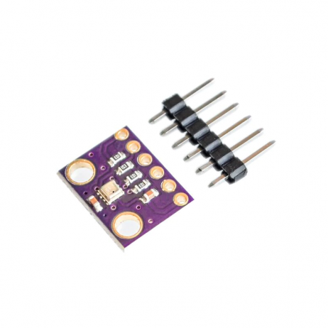
GY-BME280-3.3 Precision Altimeter Atmospheric Pressure Sensor Module
The BME280 provides temperature, humidity, and pressure all over I2C — an essential sensor for multi-sensor ESP32 weather station projects.
Resolving I2C Address Conflicts
Address conflicts occur when two I2C devices share the same default address. For example, using two BME280 sensors on the same bus, or combining a DS3231 RTC and an MPU6050 (both default to 0x68). Here are the solutions.
Method 1: Change Address via ADDR Pin
Many I2C modules have a solder bridge or jumper to change the address. For the BME280:
- SDO → GND = address 0x76 (default)
- SDO → VCC = address 0x77
This allows you to put two identical sensors on the same bus by setting one to each address.
Method 2: Use Two Separate I2C Buses
The ESP32 has two hardware I2C controllers. You can run two independent buses, each with its own set of devices:
#include <Wire.h>

// First I2C bus - default
TwoWire I2C_1 = TwoWire(0);
// Second I2C bus - custom pins
TwoWire I2C_2 = TwoWire(1);

void setup() {
  // Bus 1: default pins
  I2C_1.begin(21, 22); // SDA, SCL

  // Bus 2: custom pins (any available GPIO)
  I2C_2.begin(25, 26); // SDA, SCL
}

// Use each bus with its sensor library:
// Adafruit_BME280 bme1; bme1.begin(0x76, &I2C_1);
// Adafruit_BME280 bme2; bme2.begin(0x76, &I2C_2);
Method 3: Use an I2C Multiplexer (TCA9548A)
The TCA9548A is an 8-channel I2C multiplexer that allows you to connect up to 8 identical devices (same address) on separate channels. You select a channel, communicate with the device, then switch to another channel. This is the most scalable solution for complex multi-sensor projects.
#define TCA9548A_ADDR 0x70

void selectChannel(uint8_t channel) {
  Wire.beginTransmission(TCA9548A_ADDR);
  Wire.write(1 << channel);
  Wire.endTransmission();
}

// Usage:
selectChannel(0); // Activate channel 0
// Communicate with device on channel 0
selectChannel(1); // Activate channel 1
// Communicate with device on channel 1
Using Two I2C Buses on ESP32
Here is a practical example of using two I2C buses simultaneously on the ESP32 — Bus 1 with a BME280 and Bus 2 with a second BME280 at the same address:
#include <Wire.h>
#include <Adafruit_BME280.h>

TwoWire bus1 = TwoWire(0);
TwoWire bus2 = TwoWire(1);

Adafruit_BME280 bme_indoor;
Adafruit_BME280 bme_outdoor;

void setup() {
  Serial.begin(115200);

  // Bus 1: GPIO21=SDA, GPIO22=SCL
  bus1.begin(21, 22, 400000);
  // Bus 2: GPIO25=SDA, GPIO26=SCL
  bus2.begin(25, 26, 400000);

  // Both BME280 at address 0x76 but on different buses!
  if (!bme_indoor.begin(0x76, &bus1)) Serial.println("Indoor BME280 not found!");
  if (!bme_outdoor.begin(0x76, &bus2)) Serial.println("Outdoor BME280 not found!");

  Serial.println("Dual I2C bus initialized!");
}

void loop() {
  float indoor_temp = bme_indoor.readTemperature();
  float outdoor_temp = bme_outdoor.readTemperature();

  Serial.printf("Indoor: %.1fC | Outdoor: %.1fC | Diff: %.1fCn",
                indoor_temp, outdoor_temp, indoor_temp - outdoor_temp);
  delay(2000);
}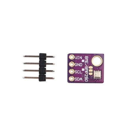
GY-BME280-5V Temperature and Humidity Sensor
This 5V-compatible BME280 module works great on the second I2C bus of your ESP32 — measure indoor and outdoor conditions simultaneously with two of these.
I2C Troubleshooting Tips
I2C issues are among the most frustrating debugging experiences for beginners. Here is a systematic approach to diagnosing and fixing ESP32 I2C problems.
Common I2C Problems and Fixes
| Symptom | Likely Cause | Fix |
|---|---|---|
| No devices found by scanner | Wrong SDA/SCL pins or no power | Verify wiring, check VCC |
| Wrong address returned | ADDR pin floating | Pull ADDR pin to GND or VCC |
| Sensor stops responding after a few minutes | I2C bus lockup due to noise | Add 100nF bypass caps near VCC/GND of each sensor |
| Garbage readings | Long wires causing signal integrity issues | Reduce clock speed to 100kHz, add stronger pull-ups |
| Error code 2 from endTransmission | NACK received — wrong address | Run scanner to confirm actual address |
I2C Bus Recovery
If the I2C bus gets locked up (SDA stuck LOW), you can recover it programmatically:
// Reset I2C bus
Wire.end();
delay(10);
Wire.begin(21, 22);
Wire.setClock(100000);
Pull-up Resistor Guidelines
- Short wires (<30cm), 1-2 devices: 4.7kΩ pull-ups (often provided on module)
- Medium length (30-100cm), 3-5 devices: 2.2kΩ pull-ups
- Long wires or many devices: 1kΩ pull-ups
- Multiple modules each with 4.7kΩ on-board pull-ups effectively reduces total pull-up resistance (parallel combination)
Frequently Asked Questions
Q1: How many I2C devices can I connect to one ESP32?
Theoretically 127 unique 7-bit addresses, but practically you are limited by bus capacitance (which causes signal degradation). With short wires and proper pull-ups, 10-15 devices on one bus is achievable. Using two buses doubles this capacity, and adding a TCA9548A multiplexer can extend to 64+ devices.
Q2: Why does my DHT11 not appear in the I2C scanner?
The DHT11 does NOT use I2C — it uses a proprietary single-wire protocol and appears on only one GPIO pin. I2C devices include BME280, SSD1306, MPU6050, DS3231, etc. Check your sensor’s datasheet to confirm its communication interface before connecting.
Q3: Can I use I2C over longer distances in an ESP32 project?
Standard I2C is designed for short distances (less than 1 meter on a PCB). For distances up to 5-10 meters, reduce the clock speed to 10-50kHz and add stronger pull-ups. For longer distances, use I2C bus extenders (like the P82B715) or switch to RS485 or CAN bus instead.
Q4: Which ESP32 pins are best for I2C in Indian IoT projects?
The default GPIO21 (SDA) and GPIO22 (SCL) are fine for most projects. Avoid GPIO0, GPIO2, GPIO15 (used for boot mode selection). If using a development board like NodeMCU-32S, refer to the pinout diagram as physical pin labels differ from GPIO numbers.
Q5: Can I mix 3.3V and 5V I2C sensors on the same ESP32 bus?
The ESP32’s GPIO pins are NOT 5V tolerant — connecting a 5V I2C sensor directly to the ESP32 can damage it. Use a logic level converter (like the BSS138-based bidirectional converter) between 5V I2C devices and the ESP32’s 3.3V I2C bus. Many sensor modules already include onboard voltage regulators and level shifters, so check the module’s voltage specifications first.
Build Your Multi-Sensor ESP32 Project
I2C makes it easy to connect multiple sensors to a single ESP32 with minimal wiring. Find BME280, BMP280, DHT sensors, and ESP32 boards at Zbotic — everything you need for your next IoT project, delivered anywhere in India.


Add comment