
A solar tracker robot using dual servos and LDR sensors is one of the most rewarding robotics projects you can build in India. Solar trackers can improve panel energy harvest by 25-40% compared to fixed installations — and building one yourself costs a fraction of commercial systems. In this complete DIY guide, you’ll learn the circuit, code, and mechanical design for a 2-axis solar tracker that automatically follows the sun from sunrise to sunset.
How Solar Trackers Work
The principle is elegantly simple: four LDR (Light Dependent Resistor) sensors are arranged in a cross pattern on the solar panel. When the panel points directly at the sun, all four LDRs receive equal illumination. When the sun moves, one pair of LDRs receives more light than the other. The controller reads the difference and drives servos to re-align the panel.
A 2-axis tracker controls both azimuth (left-right, horizontal axis) and elevation (up-down, vertical axis), allowing it to follow the sun’s complete arc across the sky. This is more effective than a 1-axis tracker which only follows one plane of motion.
The key advantage of the LDR-based approach over a GPS/RTC time-based tracker is that it is self-correcting — clouds, reflections, and atmospheric refraction are automatically handled because the system responds to actual light, not a calculated sun position.
Components Required
| Component | Specification | Qty |
|---|---|---|
| Servo Motor | SG90 (for small panels) or MG996R (for panels up to 20W) | 2 |
| LDR Sensor | 5mm standard photoresistor, 10kΩ in dark | 4 |
| Microcontroller | Arduino Uno / Nano or ESP32 | 1 |
| Resistors | 10kΩ (for LDR voltage dividers) | 4 |
| Solar Panel | 5W–20W, 12V (or 6V for small demo) | 1 |
| Power Supply | 5V 2A (USB or regulator from solar panel) | 1 |
| Divider/Barrier | Cross-shaped shadow divider (cardboard or 3D printed) | 1 |
| Frame | Acrylic or aluminium angle bracket | 1 set |
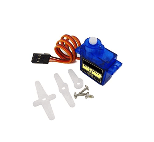
TowerPro SG90 180 Degree Rotation Servo Motor
Lightweight 9g servo perfect for small solar tracker builds. 180° rotation range and easy PWM control from any Arduino or ESP32.
LDR Sensor Circuit Design
Each LDR forms a voltage divider with a 10kΩ fixed resistor. The output voltage (at the midpoint) feeds into an analog input of the Arduino:
5V ---[LDR]---+---[10kΩ]--- GND
              |
           Analog Pin (A0, A1, A2, A3)
When more light hits the LDR, its resistance falls and the analog voltage rises. Label your four sensors as:
- LDR_TL (Top-Left) → A0
- LDR_TR (Top-Right) → A1
- LDR_BL (Bottom-Left) → A2
- LDR_BR (Bottom-Right) → A3
Mount the four LDRs at the corners of the solar panel with a cross-shaped divider (roughly 3-4 cm tall) in the centre. This divider creates the shadow that lets the system detect which direction the light is coming from — without it, all four sensors always read the same value.
2-Axis Mechanical Design
The mechanical assembly is a pan-tilt platform. Here’s how to arrange it:
- Base servo (azimuth): Mount horizontally on a fixed base. Its output shaft rotates the entire upper assembly left and right.
- Tilt servo (elevation): Mount on a bracket attached to the base servo horn. Its output shaft tilts the solar panel up and down.
- Panel mount: Attach to the tilt servo horn. Position the LDR cross at the centre of the panel face.
For small demo builds (up to a 5W panel), SG90 servos and a 3D-printed or acrylic pan-tilt bracket work perfectly. For panels above 10W, upgrade to MG996R metal-gear servos which can handle the extra torque. Always add a counterbalance weight opposite to the panel to reduce servo load and improve tracking stability.
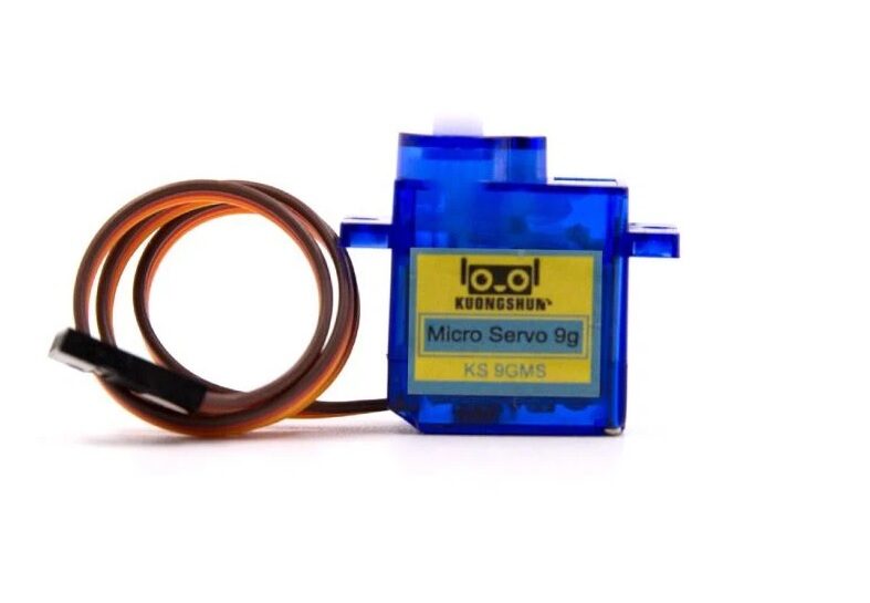
Servo SG90 9g 180 Degree
Budget-friendly SG90 servo for solar tracker elevation and azimuth axes. Good starting point for demo and school project builds.
Arduino Code for Dual Servo Control
Here is the complete Arduino sketch for the 2-axis LDR solar tracker:
#include <Servo.h>

Servo servoH;  // Horizontal (azimuth)
Servo servoV;  // Vertical (elevation)

const int LDR_TL = A0, LDR_TR = A1;
const int LDR_BL = A2, LDR_BR = A3;
const int TOLERANCE = 30;  // Dead band (tune to your hardware)
const int SERVO_DELAY = 15; // ms between steps
const int SERVO_STEP = 1;   // degrees per correction step

int posH = 90, posV = 90;   // Start at centre

void setup() {
  servoH.attach(9);
  servoV.attach(10);
  servoH.write(posH);
  servoV.write(posV);
  delay(1000);
}

void loop() {
  int tl = analogRead(LDR_TL);
  int tr = analogRead(LDR_TR);
  int bl = analogRead(LDR_BL);
  int br = analogRead(LDR_BR);

  int avgTop    = (tl + tr) / 2;
  int avgBottom = (bl + br) / 2;
  int avgLeft   = (tl + bl) / 2;
  int avgRight  = (tr + br) / 2;

  // Vertical correction
  int diffV = avgTop - avgBottom;
  if (abs(diffV) > TOLERANCE) {
    posV += (diffV > 0) ? SERVO_STEP : -SERVO_STEP;
    posV = constrain(posV, 10, 170);
    servoV.write(posV);
  }

  // Horizontal correction
  int diffH = avgLeft - avgRight;
  if (abs(diffH) > TOLERANCE) {
    posH += (diffH > 0) ? -SERVO_STEP : SERVO_STEP;
    posH = constrain(posH, 10, 170);
    servoH.write(posH);
  }

  delay(SERVO_DELAY);
}
Key parameters to tune:
- TOLERANCE: Increase if the servos hunt/jitter. A value of 20-50 works for most builds.
- SERVO_STEP: Smaller values (1°) give smoother but slower tracking. Larger values (2-3°) are faster but may overshoot.
- SERVO_DELAY: Sets tracking update rate. 15-30 ms is typical.
Calibration and Tuning Tips
Getting a solar tracker to run smoothly requires a bit of field calibration:
- Match LDR values: Not all LDRs are identical. In a dark room, measure all four readings and note any offsets. Add correction constants to your code.
- Shadow divider height: Taller dividers (5-6 cm) give more sensitivity but reduce operating range. Start with 3 cm and adjust.
- Dead zone: The TOLERANCE constant creates a dead band. Too small → constant jitter, consuming servo life. Too large → lazy tracking and energy loss. Sweet spot is usually 15-40 ADC counts.
- Night-time handling: Add a threshold: if all LDR readings are below (say) 100, park the servos at a default position (east-facing at 30° elevation for India) and stop tracking until dawn.
- Cloud recovery: If all sensors read roughly equal (overcast), the tracker should hold its last position rather than hunting.
India-Specific Build Tips
Building a solar tracker in India comes with some unique considerations:
- Sun path: India lies between 8°N and 37°N latitude. At tropical latitudes, the sun’s arc is nearly overhead — ensure your elevation servo can reach 85-90° at noon in summer.
- Monsoon proofing: If building a permanent outdoor installation, use IP65-rated enclosures for electronics. Conformal coat the PCB. Use stainless steel hardware.
- Servo corrosion: Cheap SG90 servos degrade quickly outdoors. For permanent builds, use sealed metal-gear servos.
- Power budget: Two SG90 servos draw up to 500mA each when moving under load. A small 5V 2A UBEC powered from the solar panel’s battery handles this well.
- LDR vs. current-sensing: For competition projects and higher accuracy, consider replacing LDRs with a small additional solar cell as the light sensor — its current output is a more linear measurement of irradiance.
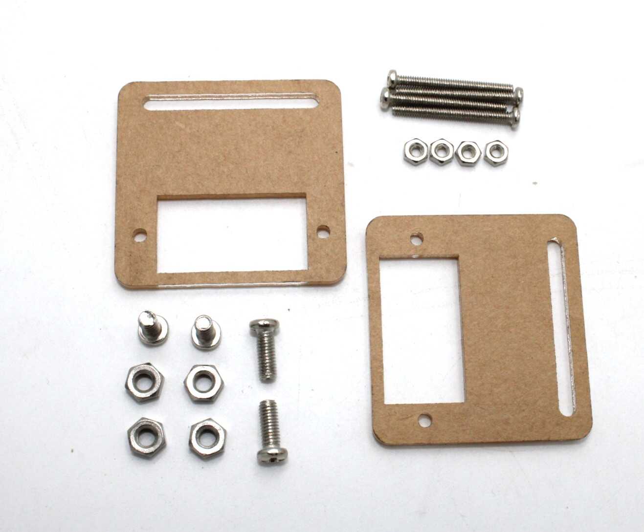
Servo Mount Holder Bracket for SG90/MG90 (Pack of 2)
Pan-tilt compatible servo mounting brackets for building the 2-axis solar tracker frame. Works with SG90 and MG90 servos.

100pcs 5mm Light Assorted DIY LEDs Kit
Handy LED kit for adding status indicators to your solar tracker (tracking active, night mode, fault indication).
Frequently Asked Questions
How much energy gain does a 2-axis solar tracker provide in India?
In most parts of India, a 2-axis tracker increases solar energy capture by 30-40% compared to a fixed south-facing tilted panel. The gain is higher in northern states with greater seasonal sun angle variation and lower in equatorial southern states where the sun is more overhead.
Can I use LM393 comparators instead of analog reading?
Yes. LM393-based LDR modules give a digital output (HIGH/LOW) when one sensor is brighter than another. This simplifies the code but removes fine control — you can only move the servo at a fixed rate, not proportionally to the error. For a smooth tracker, analog reading (ADC) is preferred.
Why does my tracker jitter continuously?
The most common causes are: TOLERANCE set too low, LDR mismatch, or vibrations from mechanical play in the servo horn. Increase TOLERANCE to 40-60, check that LDRs are matched, and add thread-lock to horn screws.
Can this design work for a 100W solar panel?
Not directly with SG90 servos — a 100W panel weighs 5-8 kg and requires industrial-grade actuators. Scale up to linear actuators or worm-gear motors with encoder feedback for panels above 50W. The LDR sensor logic remains the same.
Is it worth adding an RTC to this design?
Yes, for production builds. An RTC + sun position algorithm can serve as a primary tracker (especially useful on cloudy days) while the LDR system handles fine correction. This hybrid approach is what commercial solar trackers use.
Get Your Solar Tracker Components
Zbotic.in stocks all the components you need to build a 2-axis solar tracker — servo motors, Arduino boards, LDR modules, mounting hardware, and more, all shipped fast across India. Start your solar robotics project today.


Add comment