
Building a custom 3S 12.6V Li-Ion battery pack from 18650 cells is one of the most rewarding and practical skills for any Indian electronics hobbyist. A properly wired BMS (Battery Management System) protects every cell from over-charge, over-discharge, and short-circuit — turning a collection of individual cells into a safe, reliable power pack. This BMS wiring for a 3S 12.6V Li-Ion tutorial covers everything from cell selection to final pack testing, step by step.
What Is a 3S Li-Ion Pack?
A 3S Li-Ion pack consists of three individual lithium-ion cells connected in series. “S” stands for series — each cell adds its voltage to the total:
- Nominal voltage: 3.6–3.7V × 3 = 10.8–11.1V
- Fully charged voltage: 4.2V × 3 = 12.6V
- Safe discharge cutoff: 3.0V × 3 = 9.0V (BMS triggers disconnect)
The capacity (mAh) of the pack equals the capacity of a single cell — the series connection adds voltage, not capacity. To increase capacity, you would connect additional cells in parallel (creating a 3S2P, 3S3P pack, etc.).
Common applications for a 3S 12.6V pack in India include: DIY power tools (converted from NiCd packs), portable LED lighting (12V LED strips work perfectly), mini solar UPS units, DIY e-bike supplementary packs, and robot power systems.
What Does a BMS Do?
A Battery Management System (BMS) is an electronic circuit that monitors and protects individual cells in a multi-cell battery pack. For a 3S pack, the BMS monitors all three cells simultaneously and performs the following protection functions:
- Over-voltage protection (OVP): Stops charging if any cell reaches ~4.25V–4.30V (above the normal 4.2V full charge). Prevents electrolyte decomposition and fire.
- Under-voltage protection (UVP): Cuts output load if any cell drops below ~2.8V–3.0V. Prevents permanent capacity loss from deep discharge.
- Over-current / short-circuit protection (OCP/SCP): Disconnects output instantly if current exceeds rated limits. Prevents thermal runaway from shorts.
- Cell balancing (on some BMS boards): Passively drains overcharged cells to keep all cells at the same voltage level during charging.
- Over-temperature protection (OTP): Present on higher-end BMS boards — uses NTC thermistor to cut off above a safe temperature threshold.
Without a BMS, an unbalanced 3S pack will have cells drifting to different states of charge over time. The weakest cell will be the first to reach the cutoff voltage, starving the other two cells of usable capacity, and eventually being driven into deep discharge or reverse-charge — causing permanent failure and potential safety hazards.
Components You Need
To build a safe 3S 12.6V pack, gather these components:
- 18650 Li-Ion cells: 3 matched cells (same brand, age, capacity — see Cell Preparation section)
- 3S BMS module: Rated for your expected load current (10A, 20A, 30A versions available). Look for one with balance wires (BM1, BM2, BM3 leads in addition to B– and P–).
- Nickel strips: For spot-welding cells together (18mm or 25mm width, 0.15mm or 0.2mm thickness)
- Spot welder or conductive adhesive: Spot welding is recommended — soldering directly to cells overheats the cell and can damage the internal separator
- Silicone insulated wire: 20–22 AWG for balance wires; 16–18 AWG for main charge/discharge wires (higher current)
- XT60 or DC barrel connector: For output connection
- Kapton tape / heat shrink tubing: For insulating exposed cell connections and finishing the pack
- Cell insulator rings: Plastic rings for the positive terminal of each 18650 cell (prevents shorts to the outer can)
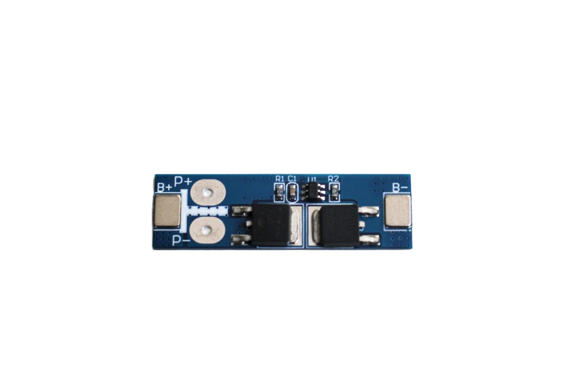
1S 12A 3.6V BMS Battery Protection Board for Li-Ion Cell
High-quality single-cell BMS protection board for 3.7V Li-Ion cells. Use three of these for individual cell protection in a 3S pack with external balancing, or choose a dedicated 3S BMS module.

1S 18650 Li-Ion BMS Charger Protection Board – 3.7V
Compact BMS protection board specifically designed for 18650 Li-Ion cells. Protects against over-charge, over-discharge and short-circuit conditions.
Cell Preparation and Matching
The quality of your finished pack depends heavily on cell matching. Using unmatched cells is the most common mistake beginners make, and it shortens pack life significantly.
Step 1: Measure each cell’s voltage
Before assembling, charge all cells to 4.2V using a known-good charger. Then measure the voltage of each cell with a multimeter 1 hour after charging. Cells should all read within 0.01V–0.02V of each other. Discard or use separately any cell that charges significantly lower.
Step 2: Check internal resistance
Ideally, use a cell tester with internal resistance (IR) measurement. Good quality 18650 cells should have IR below 100mΩ. Higher IR cells will heat more under load and discharge faster. Match cells with similar IR values.
Step 3: Capacity test
For critical applications, discharge each cell at a controlled current (0.5A) and measure the total capacity (mAh) to the 3.0V cutoff. Match cells within 50–100mAh of each other.
For casual hobby projects, matching by voltage (Step 1) is usually sufficient. For high-current or long-life packs (e-bike, power tool), do all three steps.
Wiring Cells in Series (3S)
Three cells in series means the negative terminal of one cell connects to the positive terminal of the next. The pack’s positive terminal is the positive of Cell 1, and the pack’s negative terminal is the negative of Cell 3.
Cell 1: (+) ── Pack positive output (+12.6V end)
Cell 1: (–) ── Cell 2: (+)
Cell 2: (–) ── Cell 3: (+)
Cell 3: (–) ── Pack negative output (0V / GND end)
The voltage at each junction point:
- Cell 3 negative (GND): 0V
- Cell 3 positive / Cell 2 negative junction: ~4.2V (= 1× cell)
- Cell 2 positive / Cell 1 negative junction: ~8.4V (= 2× cell)
- Cell 1 positive (Pack +): ~12.6V (= 3× cell)
These junction points (0V, 4.2V, 8.4V, 12.6V) become the balance tap points that the BMS uses to monitor each individual cell.
Important soldering note: If you cannot spot-weld, use a hot soldering iron (400°C+), pre-tin both surfaces, and complete each solder joint in under 2 seconds. Keep the iron on the cell terminal as briefly as possible. Never solder near the cell’s positive vent (top centre disc) — heat here can release the internal pressure vent.
Connecting the BMS
A typical 3S BMS module has these connection points:
- B– (Battery negative): Connects to Cell 3 negative (pack GND)
- BM1 or B1 (Balance wire 1): Connects to Cell 3 positive / Cell 2 negative junction (~4.2V)
- BM2 or B2 (Balance wire 2): Connects to Cell 2 positive / Cell 1 negative junction (~8.4V)
- BM3 or B3 (Balance wire 3): Connects to Cell 1 positive (pack +, ~12.6V)
- P– or C– (Protected negative output): This is where your load’s negative connects. NOT directly B–.
- P+ or the pack’s positive: Often the pack positive (Cell 1 +) connects directly to both the charger/load positive and BM3. Check your specific BMS schematic.
Complete 3S BMS Wiring Diagram:
Cell 1(+) ──── Pack + output ──── Charger + / Load +
Cell 1(–) ──┬── Cell 2(+) ──── BM3 on BMS
            │
Cell 2(–) ──┬── Cell 3(+) ──── BM2 on BMS
            │
Cell 3(–) ──┬────────────────── B– on BMS
                              │
                              └── BM1 on BMS (some boards tie B– to BM1)

P– on BMS ──────────────────── Load – (NOT directly to battery)
Charger – ──────────────────── C– on BMS (same P– on combined BMS)
Critical note: The load and charger MUST connect through the BMS P– (protected output), not directly to B–. Connecting load directly to B– bypasses all BMS protection. On most hobby-grade 3S BMS boards, P– and C– are combined into a single pad.
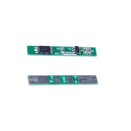
1S 3.7V 2A 1MOS BMS Li-Ion 18650 Battery Protection Board
Compact single-cell BMS for 18650 cells. Use as a per-cell protection board in advanced builds, or as a standalone protection circuit for any 3.7V application.
Charging the 3S Pack
A 3S Li-Ion pack must be charged to exactly 12.6V (4.2V × 3) using a CC/CV charger designed for 3S lithium cells. Do NOT use a general 12V power supply — a standard 12V supply outputs ~12V and will not fully charge your cells (they need 12.6V), and it also lacks the voltage limiting that prevents overcharge.
Option 1: Dedicated 3S Balance Charger
A balance charger (like the ISDT 608AC) connects to both the main pack terminals and the individual balance wires. It charges in CC/CV mode and monitors each cell independently, stopping if any cell reaches 4.2V. This is the safest and most recommended method.
Option 2: Type-C Booster Module for 3S
For a self-contained charging solution integrated into the pack, a Type-C to 3S 12.6V booster charging module provides CC/CV output regulated to 12.6V from a USB-C source. This is ideal for portable packs that need convenient USB-C charging.
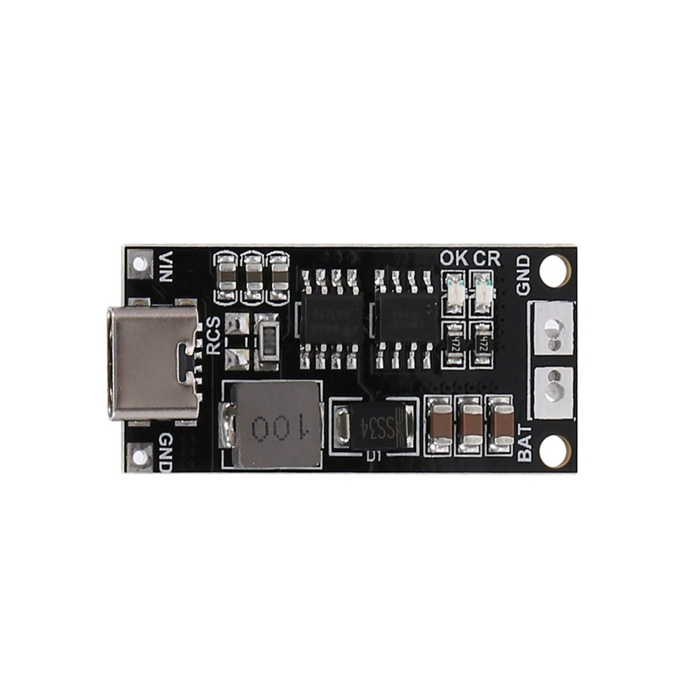
18650 Type-C to 3S 12.6V 2A Booster Charging Module
Charge your 3S 12.6V Li-Ion pack directly from any USB-C source. Outputs regulated CC/CV 12.6V at 2A — perfect for portable packs that need USB-C charging convenience.
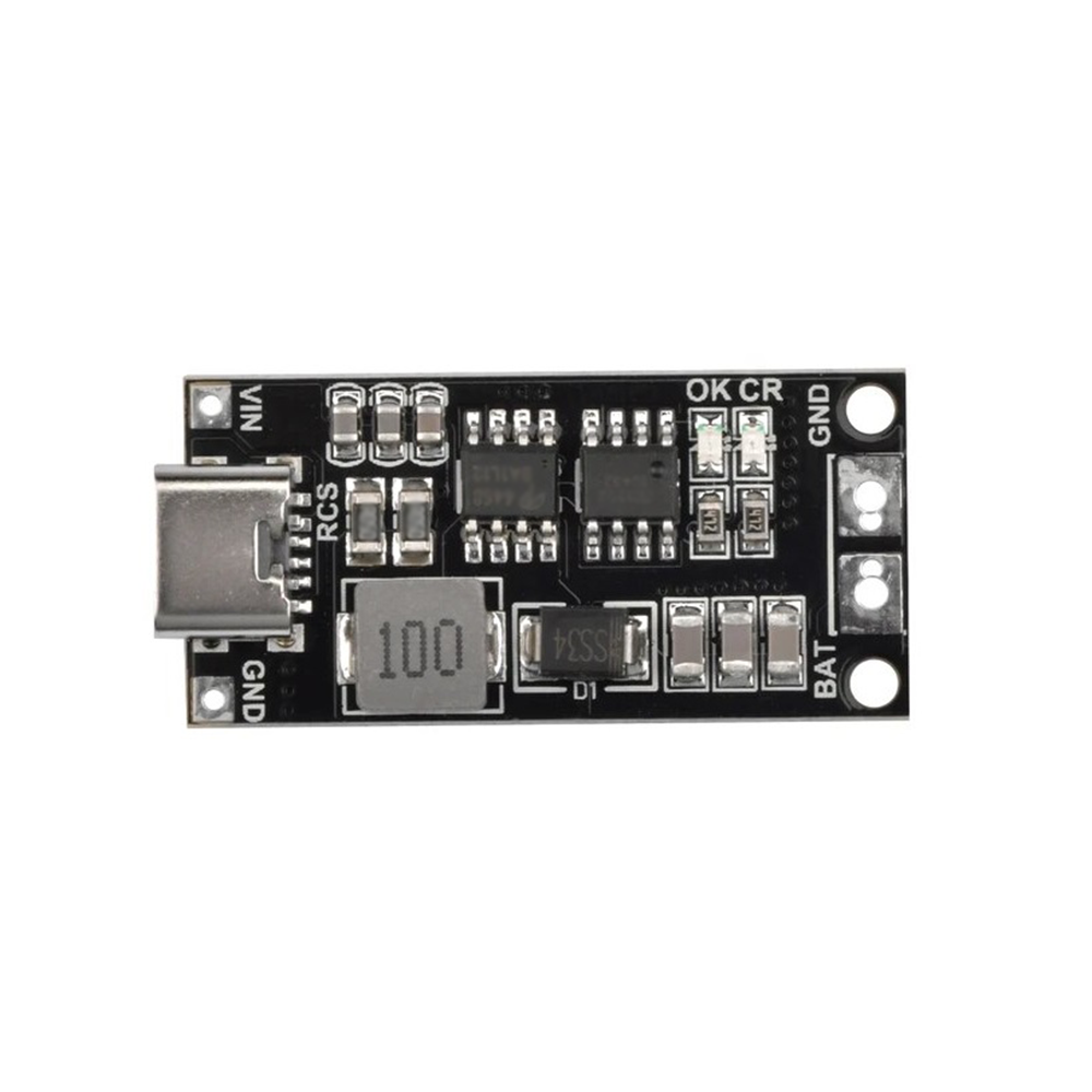
18650 Type-C to 3S 12.6V 4A Booster Charging Module
Higher-current version at 4A — charges a 3S 2600mAh pack to full in under 2 hours. Use with a USB-C PD charger that supports 9V output for best results.
Testing and Safety Checks
Before using your assembled 3S pack, perform these tests:
Test 1: No-load voltage check
Measure pack voltage (P+ to P–). Should read between 9V (fully discharged) and 12.6V (fully charged). With new cells stored at 50%, expect ~11.1V.
Test 2: Balance wire voltage check
Measure each balance point relative to pack negative:
- B– to BM1: ~3.7V (Cell 3 voltage)
- B– to BM2: ~7.4V (Cell 3 + Cell 2)
- B– to BM3: ~11.1V (all three cells)
If readings are unexpected, recheck your wiring before proceeding.
Test 3: Protection circuit test (short-circuit)
Carefully touch a short wire between P+ and P– (NOT B+ and B–). The BMS should instantly disconnect the output. Wait 3–5 seconds, then re-measure P+ to P– — the voltage should recover (BMS auto-resets on most hobby boards). If the short does not trip the BMS, the protection circuit is not functioning correctly.
Test 4: First charge
Charge the pack slowly (at 0.5C or lower) for the first charge. Monitor the temperature of all three cells with your hand — they should be warm at most, never hot. Stop immediately if any cell becomes hot to touch.
Frequently Asked Questions
What current rating should my 3S BMS have?
Choose a BMS rated for at least 1.5× your maximum expected load current. For example, if your load draws 10A peak, use a 15A or 20A BMS. Most hobby 3S BMS modules are rated 10A–40A. Higher-rated BMS boards use multiple MOSFET pairs and have better thermal handling.
Can I add more cells in parallel to increase capacity?
Yes — this creates a 3S2P (if you add one more set of 3 matched cells in parallel) or 3S3P configuration. The parallel cells must be at the same voltage before connecting (within 0.05V). Connect all positive terminals together first, then all negatives, then wire to the BMS. The BMS current rating must be higher for parallel packs as total capacity increases.
My BMS cuts off after a few minutes under load. What is wrong?
This is usually an over-current trip. Your load is drawing more current than the BMS is rated for. Check your load’s current consumption and compare it to the BMS rating. If the BMS is correctly rated, check cell internal resistance — high-IR cells heat up under load, and some BMS boards have thermal cutoff that trips early.
How do I store a 3S pack when not in use for several weeks?
Discharge the pack to approximately 11.1V (3.7V per cell — the nominal/storage voltage). Most balance chargers have a storage charge mode that charges or discharges to exactly this voltage. Store in a cool, dry location — avoid temperatures above 35°C (common in Indian summers). Never store fully charged or fully depleted.
Is it safe to build this pack at home without a spot welder?
Yes, but proceed carefully. Without a spot welder, use soldering with short contact time to avoid heating the cell body. Use copper braid or nickel strips with conductive adhesive for low-current applications. For high-current packs (above 10A), invest in a spot welder or have the pack spot-welded by a local electronics fabricator — the low-resistance nickel strip connections are critical for safety at high currents.
Shop BMS boards, 18650 holders, Type-C charging modules and all the components you need for your custom Li-Ion pack at Zbotic — fast shipping across India.

Add comment