
Battery Spot Welder DIY: Build with 18650 Cells and MOSFET
If you’ve ever tried to build your own lithium battery pack, you already know soldering directly onto battery terminals is dangerous — it heats the cell and can cause permanent damage or even fire. A battery spot welder DIY with 18650 cells solves this perfectly by delivering a short, high-current pulse through a thin nickel strip to fuse it to the battery terminal without heating the cell. In this guide, we’ll walk you through building a reliable, low-cost spot welder using surplus 18650 cells and MOSFETs — a favourite weekend project among Indian makers and EV hobbyists.
How Battery Spot Welding Works
Spot welding works on a beautifully simple principle: pass a very large current (200–1000 A) through two pieces of metal for a very short time (5–50 ms). The resistance at the contact point generates intense, localised heat that fuses the metals together without significantly heating anything else nearby.
For 18650 lithium cells, you’re typically welding a 0.1–0.2 mm nickel strip to the positive or negative terminal. The cell itself barely warms because the pulse is so brief. A DIY spot welder built from parallel 18650 cells can easily deliver 300–600 A — more than enough to weld standard nickel strips.
The key challenge is controlling when and how long the pulse fires. That’s where the MOSFET circuit comes in. MOSFETs (Metal-Oxide-Semiconductor Field-Effect Transistors) act as ultra-fast electronic switches that can open and close in microseconds, giving you precise pulse control.
Components Required
Here’s what you need to build a practical DIY spot welder for 18650 battery packs:
- Energy source: 8–16 x 18650 cells wired in parallel (the more cells, the better the current delivery). Aim for at least 60–80 Ah combined capacity for consistent welds.
- MOSFETs: IRFP4568 or IRFB4410 x 4–6 in parallel (or similarly rated N-channel MOSFETs with Vds ≥ 100V, Id ≥ 100A, low Rds(on)). IRFP4568 is ideal — Rds(on) = 4.4 mΩ, Id = 171A.
- Gate driver: IR2101 or a simple 555 timer circuit / Arduino-based timer for pulse generation (5–50 ms adjustable).
- Copper busbars: 6–10 mm² copper wire or busbars for the high-current path — do not use regular hookup wire here.
- Welding electrodes: Pure copper or copper-tungsten rods, 3–4 mm diameter, as welding tips.
- Nickel strips: 0.1 mm or 0.15 mm pure nickel strip, 8–10 mm wide.
- BMS board: 1S or multi-series BMS for the source battery pack to protect cells during discharge.
- Pushbutton: Momentary pushbutton or foot switch to trigger the weld pulse.
- Enclosure: Any sturdy plastic or metal enclosure — many makers use a project box or repurpose a PVC junction box.

1S 18650 Li-ion Lithium Battery BMS Charger Protection Board for 3.7V Battery
Protects your source 18650 cells from over-discharge and short-circuit during high-current welding pulses. Essential for the energy source pack in your DIY spot welder.
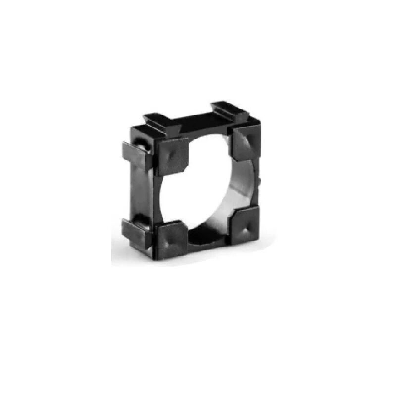
1 x 18650 Battery Holder with 18.4MM Bore Diameter – Pack of 4
Sturdy individual 18650 cell holders for assembling your spot welder energy pack. Wire multiple holders in parallel for maximum current delivery.
Circuit Design: MOSFET Pulse Control
The core circuit has two sections: the power path and the control path.
Power Path
Your 18650 cells (connected in parallel to keep voltage at ~3.7V) connect to the drain of your parallel MOSFETs. The source connects through a thick copper cable to one welding electrode. The other electrode connects directly back to the battery negative. When the MOSFETs switch on, current flows: Battery+ → MOSFET drain → MOSFET source → Electrode 1 → Nickel strip → Electrode 2 → Battery−. The nickel strip fuses at the contact points.
Control Path (Pulse Timer)
The simplest approach uses an Arduino Nano or a 555 timer:
- Arduino-based (recommended): Press a button, Arduino drives a gate driver IC (e.g., TC4427 or bootstrap driver), which then drives MOSFET gates to 10–12V above source for 5–50 ms. Use
delayMicroseconds()for sub-millisecond accuracy. A potentiometer adjusts pulse width. - 555 Timer monostable: Configure the 555 in monostable mode — a button trigger fires a single pulse of duration T = 1.1 × R × C. Adjust R (10 kΩ pot) to tune from 5–100 ms. Output feeds gate driver → MOSFETs.
Gate Drive Voltage
This is the most critical detail beginners miss. MOSFETs need 10–12V on the gate (relative to source) to turn on fully. Since your source battery is only 3.7V, you have two options:
- Use a separate 9–12V supply (4 x AA cells, or a small DC-DC booster) just for the gate drive circuit.
- Use a gate driver with a built-in charge pump, but this adds complexity.
A separate 9V battery for gate drive is the simplest and most reliable approach for a first build.
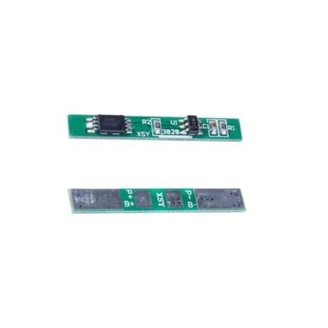
1S 3.7V 2A 1MOS BMS Li-ion 18650 Battery Protection Board
Compact BMS protection board for single 18650 cells. Use one per cell group in your spot welder source pack to prevent over-discharge.
Step-by-Step Build Instructions
- Assemble the source battery pack: Wire 10–16 fully charged 18650 cells in parallel. Use nickel strip or thick copper wire for the bus connections. Ensure all cells are at the same voltage (within 0.05V) before paralleling.
- Mount MOSFETs on a heatsink: Four IRFP4568s in parallel on a common aluminium heatsink. Insulate gate and source pins electrically from the heatsink if it’s used as a drain connector (common-drain mounting). Apply thermal paste.
- Build the pulse control board: Assemble your Arduino timer circuit on a small perfboard. Add a 10 kΩ potentiometer for pulse width adjustment and a 16×2 LCD or simple LED for feedback. Wire the gate drive output to all MOSFET gates through individual 10Ω gate resistors (prevents oscillation).
- Fabricate the welding cables: Use 6 AWG or thicker silicone-jacketed wire. Keep the positive cable (from MOSFETs) and negative cable short — under 30 cm each — to minimise resistance and inductance. Terminate each with a copper electrode holder.
- Make welding tips: Sharpen copper or copper-tungsten rods to a blunt point. A spring-loaded pen mechanism helps maintain consistent electrode pressure.
- Test with a multimeter first: Before welding a real battery, short the tips together and verify you get a brief current pulse (you’ll see a spark or hear a click). Adjust pulse width to 15–25 ms for 0.1 mm nickel strip.
- First weld test: Place nickel strip on a sacrificial 18650. Apply light pressure on both tips, press the trigger. The weld should be bright and clean with no black scorch marks. If the strip peels easily, increase pulse width by 5 ms increments.
Choosing the Right Nickel Strip
Not all nickel strip is equal. Many cheap strips sold online are actually nickel-plated steel, which welds poorly and has much higher resistance (bad for battery packs). Here’s how to choose:
- Pure nickel vs nickel-plated steel: Test with a magnet — steel strip is strongly magnetic. Pure nickel is only weakly magnetic.
- Thickness: 0.1 mm for single-layer connections in small packs; 0.15–0.2 mm for double-layer connections in high-current packs (e-bikes, power walls).
- Width: 8 mm or 10 mm is standard. Wider strips carry more current.
- Perforation: Pre-perforated strips are easier to weld (the electrode tips centre through the holes), but solid strips are fine too.
Safety Precautions
A spot welder with 16 parallel 18650 cells can deliver over 500A for milliseconds. Treat it with respect:
- Never short the terminals directly. Even briefly, this can cause cells to vent, catch fire, or explode. Always have a fuse (100A automotive fuse) in series with the battery positive.
- Work in a ventilated area. Welding produces tiny metal vapour particles and ozone.
- Wear safety glasses. Sparks are common, especially if tips are poorly aligned.
- Keep a fire extinguisher nearby. Lithium fires require a Class D or dry sand extinguisher — a regular CO₂ extinguisher won’t work effectively on lithium.
- Discharge cells before disassembly. After a project, bring cells down to storage voltage (3.6–3.8V) rather than leaving them fully charged.
- Use insulated copper cables. Any accidental contact between bare positive and negative cables generates massive arcing.
- Monitor cell temperatures. After a long welding session, feel the cells. If any are noticeably warm, stop and allow them to cool.
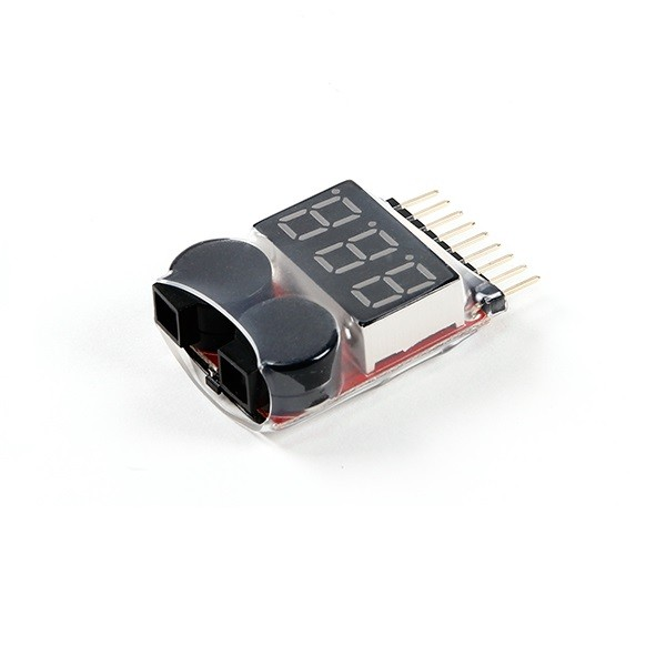
1-8S Lipo Battery Voltage Tester without Alarm
Check individual cell voltages in your spot welder source pack quickly and easily. Ensures all parallel cells are balanced before use.
Calibrating Pulse Time for Clean Welds
Getting the pulse duration right is an art. Start conservative and work up:
| Nickel Strip Thickness | Recommended Pulse (Single) | Double Pulse Option |
|---|---|---|
| 0.1 mm | 10–20 ms | 5 ms + 15 ms (50 ms gap) |
| 0.15 mm | 20–35 ms | 8 ms + 25 ms |
| 0.2 mm | 35–50 ms | 10 ms + 40 ms |
Double-pulse technique: A short pre-pulse cleans the surface and preheats the metal, and the main pulse does the actual weld. This gives stronger, more consistent welds and is used in commercial welders. With an Arduino, it’s easy to implement: pulse(5); delay(50); pulse(20);
Signs of a good weld: The strip doesn’t peel with finger pressure, the weld spot appears silver/bright (not black), and there’s no visible gap around the contact points. A bad weld looks burnt or the strip lifts with minimal force.
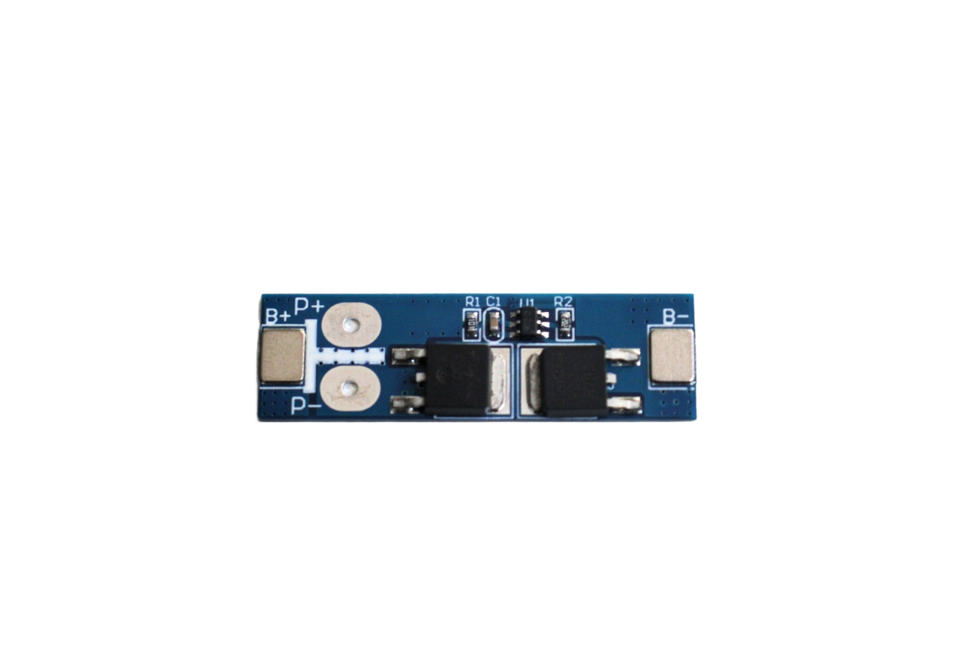
1S 12A 3.6V BMS Battery Protection Board for Li-ion Cell
Higher current BMS rated to 12A for robust protection. Suitable for heavier source packs in your spot welder build.
Frequently Asked Questions
How many 18650 cells do I need for a DIY spot welder?
A minimum of 8 parallel 18650 cells (around 20–25 Ah combined) can produce welds on 0.1 mm nickel strip. For reliable welds on 0.15–0.2 mm strip, use 12–16 cells. More cells mean lower internal resistance, cleaner pulses, and stronger welds. Salvaged laptop battery cells work well if tested for capacity and internal resistance first.
Can I use a car battery instead of 18650 cells?
Yes, a 12V lead-acid car battery delivers enormous current and can be used for spot welding. However, it’s much heavier, less portable, and requires extra care to not over-discharge it. The MOSFET control circuit works exactly the same way. A 12V source also means your gate drive voltage is available directly from the battery, simplifying the control circuit.
Why are my welds burning the nickel strip black?
Black burn marks usually mean your pulse is too long, electrode pressure is too light (causing high resistance at the contact), or your electrodes are dirty/oxidised. Reduce pulse by 5 ms, clean your tips with fine sandpaper, and press slightly harder. Nickel-plated steel strip (common in cheap packs) also tends to burn more than pure nickel.
What MOSFET should I use for a DIY battery spot welder?
The IRFP4568 is a popular choice — it has an Rds(on) of just 4.4 mΩ and handles 171A continuous (more in short pulses). IRFB4410 and IRFB3207 are also commonly used. Wire 4–6 of them in parallel with individual 10Ω gate resistors. Avoid logic-level MOSFETs unless you’re using a proper gate driver with sufficient drive voltage.
Is a DIY spot welder legal to build in India?
Yes, building a DIY battery spot welder for personal use is completely legal in India. It’s a popular maker project. Just follow standard electrical safety practices. If you plan to sell battery packs commercially, you may need to comply with BIS standards for the final product, but the welder itself is a personal tool.
Ready to Build Your Battery Spot Welder?
Get all the components you need — 18650 battery holders, BMS protection boards, and voltage testers — from Zbotic. We stock quality electronics components trusted by thousands of Indian makers and engineers.


Add comment