
The balancing cube robot reaction wheel is one of the most mesmerising robotics projects you can build. A cube that appears motionless tips to one face, senses it’s falling, spins up internal reaction wheels to arrest the fall, and rights itself — all within milliseconds. Unlike a wheeled balancing robot that needs floor contact to stabilise, the reaction wheel cube floats on any surface, defying gravity through pure angular momentum. This guide walks through the physics, electronics, and mechanical assembly of a six-motor self-righting cube you can build in India using locally available components.
The Physics of Reaction Wheels
A reaction wheel works on the principle of conservation of angular momentum. When the motor spins its flywheel in one direction, the chassis experiences an equal and opposite torque. In a spacecraft, a single reaction wheel can control rotation around one axis. In a balancing cube, we need to control rotation around three orthogonal axes — so three reaction wheels, each perpendicular to the others, is the theoretical minimum. A six-motor design, placing two wheels per axis, doubles the available torque while keeping the system symmetric and reducing the risk of motor saturation during aggressive manoeuvres.
The key equation is: τ_chassis = -I_wheel × α_wheel, where τ is torque, I is the flywheel’s moment of inertia, and α is the angular acceleration of the motor. To maximise torque with a small cube, you want a flywheel with high rotational inertia (heavy, large radius) and a motor capable of high angular acceleration (high peak torque-to-inertia ratio). This is why gimbal brushless motors — designed for smooth, fast angular motion — are ideal for this application.
Six-Motor Architecture Explained
A six-motor cube places one brushless motor + flywheel assembly on each of the six inner faces. Motors on opposite faces control the same axis but spin in opposing senses, meaning when one spins clockwise the other spins counter-clockwise relative to the cube frame. This allows you to either double the torque (both motors accelerate in the same effect direction) or cancel net torque (for hover-balance without axis drift).
Each motor is connected to a BLDC ESC (Electronic Speed Controller) that accepts a PWM signal from the main microcontroller. An MPU-6050 IMU (gyroscope + accelerometer) provides the orientation feedback needed to close the control loop. The microcontroller runs a PID algorithm: reads the IMU, computes error from level, and outputs corrective motor commands faster than gravity can act — typically at 500 Hz or higher.

2805 140KV Gimbal Brushless Motor
A low-KV gimbal brushless motor ideal for reaction wheel applications — smooth torque delivery and excellent low-speed control.
Full Components List
Here’s what you need to build a 15 cm aluminium cube:
- 6× Gimbal brushless motors (2804 or 2805, 140–260 KV) + matching flywheels
- 6× 30A BLDC ESC (with active braking, bidirectional mode)
- 1× MPU-6050 IMU module
- 1× Arduino Mega or ESP32 (for 6+ PWM outputs and fast loop)
- 1× 3S LiPo battery 1500–2200 mAh + XT60 connector
- Aluminium or PETG 3D-printed cube frame (approx. 15×15×15 cm)
- M3 standoffs, bolts, and vibration-damping mounts
- 20 AWG silicone wire + bullet connectors
- 5V BEC or DC-DC step-down for logic power
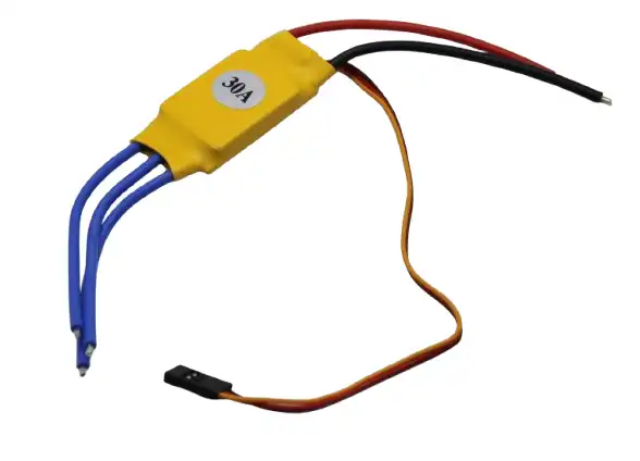
30A BLDC ESC Brushless Electronic Speed Controller
A 30A ESC capable of driving gimbal motors bidirectionally with fast throttle response — essential for reaction wheel control.
Mechanical Assembly
Start with the cube frame. A 15 cm aluminium square tube frame offers the best strength-to-weight ratio. Cut six identical square panels with a central mounting hole for the motor can, and four corner holes for M3 bolts to the frame. Leave at least 3 cm of internal clearance on each axis so the flywheel can spin freely without touching the internal electronics.
Mount each motor perpendicular to its face panel. The flywheel (typically a laser-cut 80–100 mm aluminium disc, 8–10 mm thick) attaches to the motor shaft via a 4 mm hex coupling. Balance each flywheel by spinning it and marking heavy spots, then drilling small weight-reduction holes on the heavy side. An unbalanced flywheel creates vibration that confuses the IMU and makes tuning nearly impossible.
Centre of gravity is critical. The entire assembly — battery, ESCs, microcontroller — must be as close to the geometric centre of the cube as possible. Off-centre weight creates a persistent static torque that the reaction wheels must constantly fight, draining motor energy and increasing temperature.
Electronics & Wiring
Run a dedicated power bus (XT30 or XT60) from the LiPo main leads to a power distribution board. All six ESCs draw from this bus. Keep ESC power wires as short as possible and twist the positive/negative pairs to reduce magnetic interference with the IMU. The IMU should be mounted at the geometric centre of the cube on vibration-isolating foam or damping washers — even small vibrations corrupt gyroscope readings at high frequency.
Connect each ESC signal wire (PWM) to a dedicated Arduino or ESP32 PWM-capable pin. The Mega has 15 PWM channels, comfortably accommodating all 6 ESCs with channels to spare. Set ESC PWM frequency to 400 Hz for faster response. Wire the MPU-6050 to I2C (SDA/SCL) with 4.7 kΩ pull-up resistors.

2204 260KV Brushless Gimbal Motor
A compact 2204 gimbal motor suitable for smaller reaction wheel cubes with good torque-to-size ratio.
Firmware & Control Algorithm
The control firmware runs as a fixed-rate interrupt loop, typically at 500 Hz to 1 kHz. Each cycle performs the following steps:
- IMU read: Fetch raw gyro and accelerometer data from MPU-6050 over I2C. Apply a complementary filter or Kalman filter to compute roll, pitch, and yaw angle estimates.
- Error computation: Calculate angular error on each of the three axes (desired angle = 0° on all axes for upright balance).
- PID calculation: Apply separate PID controllers for each axis. The output is a desired angular acceleration for the reaction wheel pair on that axis.
- Motor command mapping: Convert PID outputs to ESC throttle values (1000–2000 µs PWM) for all six motors. Opposite-face motor pairs receive complementary commands.
- Output: Write PWM values to all six ESC channels simultaneously.
A key implementation detail: ESCs configured for bidirectional mode require a specific arming sequence and typically have a neutral point at 1500 µs. Your PID output should be mapped such that 0 torque request = 1500 µs, maximum positive torque = 2000 µs, maximum negative torque = 1000 µs.
PID Tuning for the Reaction Wheel Cube
Tuning a 3-axis PID for a balancing cube is more challenging than a simple line-follower PID because the three axes are mechanically coupled — aggressive correction on one axis disturbs the others. Follow this sequence:
- Start with derivative gain (D): For a reaction wheel system, D is your primary damping. Set P and I to zero. Increase D until the cube resists being pushed without oscillating. High D with zero P means the cube fights rotational velocity rather than position error.
- Add proportional gain (P): Slowly increase P until the cube returns to upright when displaced. Too much P causes oscillation around the setpoint.
- Add integral gain (I) last and sparingly: I corrects steady-state offset (e.g., off-centre battery). Set I too high and the cube winds up and topples. A very small I term (0.001–0.01) is usually sufficient.
- Tune each axis independently: Lock two axes mechanically (cardboard wedges work) and tune the free axis. Then unlock all axes and fine-tune interactions.
Frequently Asked Questions
Why use six motors instead of three for the balancing cube?
Three motors are the theoretical minimum, but six motors provide doubled torque per axis and allows the control algorithm to distribute torque more evenly, preventing any single motor from saturating (reaching maximum speed with no remaining control authority). Six motors also provide redundancy — the cube can still balance if one motor fails, at reduced authority.
What is the ideal flywheel material for a DIY reaction wheel cube in India?
Aluminium alloy (6061 or 5083) is ideal — high density, machinable at any local metal workshop, and resistant to the centrifugal stresses at typical operating speeds. Laser-cut steel is denser but heavier for shipping and harder to balance. Avoid 3D-printed PLA/PETG flywheels as they flex at speed and introduce vibration.
Can I use standard quadcopter ESCs for the reaction wheel motors?
Standard quadcopter ESCs only spin in one direction (unidirectional), which means you can only apply torque in one sense per motor. For a bidirectional reaction wheel, you need either: (a) ESCs specifically configured for bidirectional (reversible) operation like SimonK/BLHeli with reversed mode, or (b) dedicated gimbal ESCs (GBGC-type) which natively support bidirectional control.
How long does the battery last in a reaction wheel cube?
A 3S 1500 mAh LiPo running six brushless motors at moderate load typically lasts 8–15 minutes of active balancing. Aggressive manoeuvres or heavy flywheels will drain the battery faster. Monitor cell voltage with a LiPo alarm to prevent deep discharge damage.
Is it possible to make a single-wheel balancing cube?
Yes — a single-axis balancing cube with one reaction wheel is a popular beginner reaction-wheel project (the “CubOne”). It balances on one corner/edge along one axis. Extending this to full 3D corner balancing requires three orthogonal wheels and a much more complex control algorithm. The six-motor version described here is best tackled after successfully building a single-axis version.
Conclusion
The balancing cube robot reaction wheel project combines control theory, mechanical precision, and electronics into one of the most visually impressive robots a maker can build. The six-motor architecture gives you ample torque margin and redundancy, making it more robust than the minimal three-wheel design. With gimbal brushless motors, quality ESCs, and a well-tuned PID loop running at 500 Hz+, your cube will self-right from any orientation and hold an eerily steady balance.
All the key components for this build — from brushless gimbal motors and ESCs to servo brackets and structural hardware — are available at Zbotic’s Robotics & DIY store with fast shipping across India.


Add comment