
If you have ever wondered how a microcontroller reads a temperature sensor or how a Bluetooth speaker turns digital audio back into sound, the answer lies in two fundamental building blocks of modern electronics: the ADC (Analog-to-Digital Converter) and the DAC (Digital-to-Analog Converter). Understanding ADC vs DAC is essential for anyone working with sensors, audio circuits, motor control, or any system that bridges the real world with digital processing.
In this comprehensive guide we will cover everything — from first principles to practical project tips — so you walk away confident about choosing and using converters in your own designs.
What Is an ADC?
An Analog-to-Digital Converter (ADC) is a circuit that samples a continuous, real-world voltage and converts it into a discrete binary number that a microprocessor or microcontroller can process. The physical world is inherently analog — temperature varies smoothly, sound waves oscillate continuously, and a potentiometer produces a continuously varying voltage. Digital systems, however, can only handle 0s and 1s. The ADC is the translator between these two worlds.
For example, if you connect an LM35 temperature sensor to an Arduino, the sensor outputs a voltage proportional to temperature (10 mV/°C). The Arduino’s built-in ADC reads that voltage and converts it to a number between 0 and 1023 (10-bit resolution), which the sketch then maps to a Celsius value.

LM35 Temperature Sensor
A classic analog temperature sensor — perfect for understanding ADC inputs on Arduino and ESP32 projects.
What Is a DAC?
A Digital-to-Analog Converter (DAC) does exactly the reverse: it takes a binary number stored in a digital system and converts it into a proportional analog voltage or current. Whenever your microcontroller needs to output a variable voltage — drive a speaker, control a servo with a precise analog signal, adjust the brightness of a backlight, or set a reference voltage — it uses a DAC (or a technique like PWM that approximates one).
Modern smartphones, Bluetooth speakers, DACs in audio amplifiers, and even CNC machine motor controllers all rely on high-quality DACs to reproduce smooth, accurate analog signals from digital data.
ADC vs DAC: Key Differences at a Glance
| Feature | ADC | DAC |
|---|---|---|
| Direction | Analog → Digital | Digital → Analog |
| Primary use | Sensing, measurement, input | Audio output, signal generation, control |
| Key metric | Sampling rate, resolution, SNR | Settling time, resolution, THD |
| Found in | Microcontrollers, oscilloscopes, sensors | Audio codecs, motor drives, signal generators |
| Hobbyist example | Reading LM35 on Arduino A0 | ESP32 DAC pin driving a speaker |
How an ADC Works Step by Step
Converting an analog voltage to a digital number happens in three stages:
1. Sampling
The ADC takes a snapshot of the input voltage at a precise moment in time. According to the Nyquist–Shannon sampling theorem, the sampling rate must be at least twice the highest frequency present in the analog signal. If you are digitising audio up to 20 kHz, you need at least 40,000 samples per second (40 kSPS). The Arduino’s ADC runs at about 9,600 SPS by default — fine for slow temperature readings but not audio.
2. Quantisation
The sampled voltage is compared against a set of discrete levels determined by the ADC’s resolution. A 10-bit ADC divides the reference voltage (say 5 V) into 2¹⁰ = 1024 steps. Each step is 5 V ÷ 1024 ≈ 4.88 mV. A 12-bit ADC gives 4096 steps (≈1.22 mV per step). The voltage is rounded to the nearest step, introducing quantisation error — an unavoidable inaccuracy inherent to the conversion process.
3. Encoding
The quantised level is encoded as a binary number and passed to the digital system. For a 10-bit ADC reading 2.5 V with a 5 V reference, the output would be 512 (binary: 1000000000).
How a DAC Works Step by Step
A DAC performs the reverse process:
- Receive binary input: The digital system writes a binary word (e.g. 10-bit, 12-bit) to the DAC.
- Weight the bits: Each bit is assigned a weighted voltage/current proportional to its significance (MSB has half the full-scale value, next bit a quarter, etc.).
- Sum the weighted values: All weighted contributions are summed to produce the output voltage.
- Smooth the output: A low-pass filter (reconstruction filter) smooths the stepped output into a clean analog waveform.
Types of ADC Architectures
Successive Approximation Register (SAR) ADC
The most common type in microcontrollers. It uses a binary search algorithm — starting from the MSB — to converge on the correct digital value in N clock cycles (where N is the bit depth). Fast, power-efficient, and accurate for medium speeds. Used in: Arduino, ESP32, STM32 built-in ADCs.
Delta-Sigma (ΔΣ) ADC
Trades speed for extremely high resolution (16–24 bits). Oversamples the input many times, uses a modulator to create a stream of 1s and 0s, then a digital filter averages them into a high-resolution result. Used in: audio codecs, precision measurement instruments, load cells.
Flash ADC
The fastest ADC architecture. Uses 2ᴺ−1 comparators simultaneously to perform conversion in a single clock cycle. Extremely fast (GSps range) but power-hungry and expensive at high resolutions. Used in: oscilloscopes, RF receivers.
Dual-Slope (Integrating) ADC
Very accurate and excellent noise rejection but slow. Charges a capacitor at the input voltage, then discharges at a known rate and counts the time. Used in: digital multimeters, bench instruments.
Types of DAC Architectures
R-2R Ladder DAC
Uses a resistor network where the values alternate between R and 2R. Simple, accurate, and easy to implement. Commonly used in standalone DAC ICs like the MCP4725 (I2C, 12-bit).
Weighted Resistor DAC
Each bit drives a resistor with a value proportional to its significance. Simple but requires very precise resistors for high bit depths.
Pulse-Width Modulation (PWM) + Filter
Many microcontrollers approximate a DAC using PWM output followed by a low-pass RC filter. Not a true DAC but works well for non-critical applications like LED dimming or simple audio.
Sigma-Delta DAC
The high-end choice for audio — same oversampling principle as ΔΣ ADC in reverse. Found in CD players, streaming DACs, and professional audio equipment.
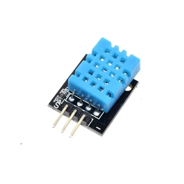
DHT11 Digital Humidity & Temperature Sensor Module
Uses a built-in ADC internally — outputs digital data over a single wire, great for learning sensor interfacing.
Key Specifications You Must Understand
Resolution (Bits)
The number of bits in the output word. More bits = finer steps = better accuracy. An 8-bit ADC has 256 levels; a 16-bit ADC has 65,536 levels. For most sensor applications 10–12 bits is sufficient. Audio typically demands 16–24 bits.
Sampling Rate / Throughput
How many conversions the ADC can complete per second (SPS or SPS). Limited by the ADC architecture and clock speed. For audio: 44.1–192 kSPS. For sensors: 1–100 SPS is usually enough.
Reference Voltage (Vref)
The upper limit of the input range the ADC can measure. Arduino uses 5 V (or 3.3 V on 3.3 V boards) as Vref. Using an external precision Vref (e.g. LM4040) dramatically improves accuracy.
Signal-to-Noise Ratio (SNR)
The ratio of the desired signal power to background noise. Higher SNR = cleaner reading. An ideal N-bit ADC achieves SNR ≈ 6.02N + 1.76 dB. Real-world noise (power supply ripple, PCB layout, digital crosstalk) degrades this.
Total Harmonic Distortion (THD) — DAC
For DACs, especially audio DACs, THD measures how much distortion the converter introduces. Lower THD (e.g. −100 dB) means a cleaner, more accurate analog output.
Integral Non-Linearity (INL) & Differential Non-Linearity (DNL)
INL measures how far the actual transfer curve deviates from an ideal straight line. DNL measures the step size variation between adjacent output codes. Both should be less than ±1 LSB (Least Significant Bit) for monotonic, glitch-free operation.
ADC in Microcontrollers: Arduino, ESP32 & More
Arduino Uno (ATmega328P)
- 6 ADC channels (A0–A5)
- 10-bit resolution, 5 V reference (or 1.1 V internal)
- Default speed: ~9.6 kSPS (can reach ~77 kSPS by adjusting the prescaler)
- Reads with
analogRead(pin)— returns 0–1023
ESP32
- Two 12-bit SAR ADCs, 18 channels total
- Input range 0–3.3 V (non-linear above ~3.1 V — use calibration)
- Also has two 8-bit DAC outputs on GPIO25 and GPIO26
Raspberry Pi Pico (RP2040)
- Three 12-bit ADC inputs + one temperature sensor channel
- 500 kSPS maximum sampling rate
- Reference: 3.3 V
External ADC ICs (when built-in isn’t enough)
When you need higher resolution or better accuracy, add an external ADC. Popular choices:
- ADS1115 — 16-bit, 860 SPS, I2C, 4 channels, programmable gain. Excellent for precision sensor work.
- MCP3208 — 12-bit, 100 kSPS, SPI, 8 channels. Budget-friendly for multiple sensor inputs.
- MCP4725 — 12-bit DAC with I2C. Common for generating analog reference voltages.
Real-World Applications
ADC Applications
- Weather stations: LM35/NTC thermistor → ADC → temperature display
- Sound level meters: Microphone → op-amp → ADC → dB calculation
- Voltage monitoring: Voltage divider → ADC → battery management system
- Motor current sensing: Shunt resistor → ADC → PID control loop
- EEG/ECG bio-signal acquisition: Instrumentation amp → Delta-Sigma ADC
DAC Applications
- Audio playback: MP3 file data → DAC → amplifier → speaker
- Function generators: Microcontroller writes sine wave lookup table to DAC → analog sine output
- Motor speed control: PWM or DAC → motor driver reference input
- LCD bias voltage generation: DAC sets the contrast voltage
- Arbitrary waveform generators: Used in RF testing, modulation systems
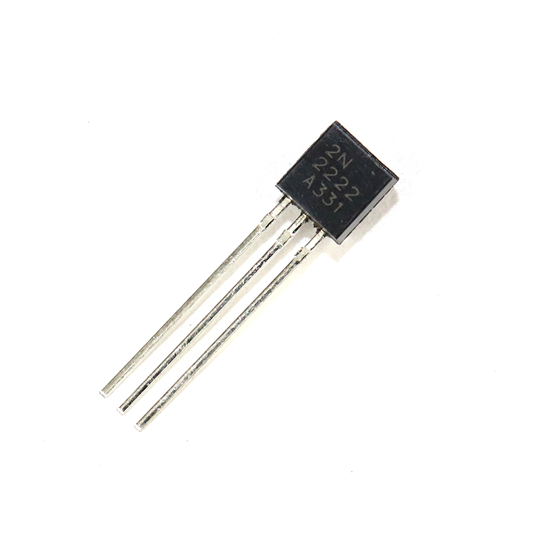
2N2222 NPN Transistor (Pack of 20)
Use with ADC output stages or DAC-driven motor control circuits for switching and amplification.
Practical Project Tips
Reduce ADC Noise on Arduino
- Add a 100 nF ceramic capacitor from AREF to GND.
- Use
analogReference(INTERNAL)for 1.1 V reference when measuring small signals. - Average multiple readings: take 16–64 samples and divide — reduces random noise by √N.
- Sample at the end of the conversion (use ADC interrupt) rather than polling.
- Keep analog traces away from digital clock lines on your PCB.
ESP32 ADC Calibration
The ESP32 ADC has a known non-linearity. Use esp_adc_cal_characterize() from the ESP-IDF ADC calibration library to compensate. The Arduino ESP32 core also provides analogReadMilliVolts() for corrected readings.
Power Your DAC from a Clean Rail
For audio DAC outputs, power the analog section from a separate, filtered supply. Switching noise from the digital supply will appear in the output spectrum as spurs.
Use Decoupling Capacitors
Place 100 nF and 10 µF capacitors close to every VCC/AVCC pin of your ADC/DAC IC. This is non-negotiable for clean conversions (we’ll cover decoupling in detail in the next article).

0.1µF Ceramic Capacitor (Pack of 50)
Essential decoupling capacitors for stable ADC/DAC performance — keep them close to power pins on your PCB.
Frequently Asked Questions
What is the difference between ADC and DAC?
An ADC converts a continuous analog voltage into a discrete digital number. A DAC does the reverse — it converts a digital number back into an analog voltage. ADCs are used for sensing and measurement; DACs are used for audio output, signal generation, and analog control.
Which microcontrollers have a built-in DAC?
ESP32 has two 8-bit DAC outputs. STM32 series microcontrollers often include 12-bit DACs. Arduino Uno and Mega do NOT have a true DAC — they use PWM instead. Raspberry Pi Pico also lacks a built-in DAC.
What resolution do I need for my project?
For general sensor reading (temperature, light, humidity): 10–12 bits is plenty. For audio: 16 bits minimum, 24 bits for professional quality. For precision instrumentation (weighing scales, medical devices): 16–24 bits with a Delta-Sigma ADC.
Can I use PWM as a DAC?
Yes, with limitations. A PWM signal followed by a low-pass RC filter generates an approximate analog voltage. It works for slow control applications like LED dimming or simple audio. However, the output has ripple (noise) and limited bandwidth — not suitable for precision measurement or high-quality audio.
Why does my Arduino ADC reading fluctuate?
Common causes: noisy power supply, floating input pin, insufficient decoupling capacitors on AVCC, digital noise coupling into analog ground, or the ADC clock prescaler set too fast. Adding a 100 nF cap on AREF and averaging 16+ readings will solve most fluctuation issues.
What is an ADC’s effective number of bits (ENOB)?
ENOB is the real-world resolution accounting for noise and distortion. A 12-bit ADC might only deliver 10–11 bits ENOB due to internal noise. Always check the datasheet’s SINAD figure: ENOB = (SINAD − 1.76) / 6.02.
Ready to start your ADC/DAC project? Pick up sensors and components at Zbotic.in — India’s trusted store for electronics hobbyists and engineers. From temperature sensors to precision resistors and capacitors, everything you need ships fast across India.


Add comment