
IR Remote Control: Build a Custom TV Remote with Arduino
Have you ever wanted to control your TV, AC, or any IR-controlled appliance with a custom IR remote control Arduino setup? Maybe you want to automate your home theatre with a single button, or build a learning remote that captures and replays signals from multiple remotes. Whatever your goal, this project guide walks you through everything — from understanding infrared communication to building a fully custom TV remote with Arduino that can mimic, learn, and transmit any IR code.
How IR Remote Control Works
Infrared remote controls work by flashing an infrared LED at a specific frequency — typically 38 kHz — in a pattern that encodes button presses. The pattern is a series of ON/OFF pulses called marks (LED on) and spaces (LED off). The total pattern encodes a protocol, device address, and command code.
An IR receiver module (like the TSOP1738 or VS1838B) on the receiving device filters for the carrier frequency (38 kHz), demodulates the signal, and outputs clean logic-level pulses representing the data. Your TV’s processor decodes those pulses using a protocol like NEC, Sony SIRC, or Philips RC5.
The good news for Arduino makers: the IRremote library handles all this modulation and demodulation for you. You only need to call a few functions to decode incoming codes or blast out custom IR commands.
Why build a custom IR remote?
- Automate home theatre with a single button (power on TV + AC + set-top box simultaneously)
- Build a universal remote that learns codes from existing remotes
- Control IR appliances from a smartphone via WiFi-to-IR bridge using ESP32
- Implement gesture-based or voice-activated control of IR devices
- Build IR-controlled RC vehicles or robots
Components You Need
Here is the full bill of materials for a custom IR remote project:
- Arduino Uno or Nano — the microcontroller brain
- IR receiver module (TSOP1738 or VS1838B) — for learning/receiving IR codes
- IR LED (940nm, T1-3/4 package) — for transmitting IR commands
- NPN transistor (2N2222 or BC547) — to drive the IR LED at sufficient current
- 100Ω resistor — base resistor for the transistor
- 10Ω–33Ω resistor — current limiting for IR LED (drives up to 100mA peak)
- Push buttons (4-6 units) — for the remote’s button interface
- 10kΩ resistors — pull-down resistors for buttons
- OLED display (optional) — to show which command is being sent
- Breadboard and jumper wires
The TSOP1738 is the standard 38 kHz IR receiver in India and is widely available. Its output pin goes HIGH when idle and LOW when it detects modulated IR light. The VS1838B is a smaller and slightly more sensitive alternative with the same pinout.
Receiving & Decoding IR Signals with Arduino
Before you can replicate a remote’s signals, you need to capture and decode them. This first sketch receives IR signals and prints the decoded protocol, address, and command to the Serial Monitor.
Wiring the IR receiver:
TSOP1738 / VS1838B:
  Pin 1 (OUT) → Arduino Pin 2
  Pin 2 (GND) → Arduino GND
  Pin 3 (VCC) → Arduino 5V

Note: Add a 100Ω resistor + 4.7µF cap on VCC for noise filtering (optional but recommended)
Install IRremote library: Open Arduino IDE → Library Manager → search “IRremote” → install IRremote by shirriff, z3t0, ArminJo (version 4.x).
IR Receiver Sketch:
#include <IRremote.hpp>

#define IR_RECEIVE_PIN 2

void setup() {
  Serial.begin(115200);
  IrReceiver.begin(IR_RECEIVE_PIN, ENABLE_LED_FEEDBACK);
  Serial.println("IR Receiver ready. Point your remote and press a button.");
}

void loop() {
  if (IrReceiver.decode()) {
    Serial.println(IrReceiver.decodedIRData.decodedRawData, HEX);
    IrReceiver.printIRResultShort(&Serial);
    IrReceiver.printIRSendUsage(&Serial);  // Prints code to resend this signal!
    IrReceiver.resume();  // Enable receiving the next value
  }
}
Open the Serial Monitor at 115200 baud. Point your TV remote at the TSOP1738 and press buttons. You will see output like:
Protocol=NEC Address=0x4 Command=0x18 Raw-Data=0xE718FB04
Send with: IrSender.sendNEC(0x4, 0x18, <numberOfRepeats>);
The library helpfully prints exactly the function call you need to replay the signal. Write down the protocol, address, and command for each button you want to replicate.
Sending Custom IR Signals
Once you have captured the codes, wiring the IR LED transmitter circuit and writing the sender sketch is straightforward.
IR LED transmitter circuit:
Arduino Pin 3 → 100Ω resistor → Base of 2N2222/BC547
Emitter of transistor → GND
Collector of transistor → Cathode of IR LED
Anode of IR LED → 33Ω resistor → 5V

Alternatively (simple, lower power):
Arduino Pin 3 → 100Ω → IR LED anode → IR LED cathode → GND
(Max ~20mA, range ~2-3m)
Note: Arduino Pin 3 is the default IR send pin for IRremote library on most AVR boards. Check the library documentation if using a different board.
Sender Sketch (NEC protocol example for Samsung/LG TV):
#include <IRremote.hpp>

#define IR_SEND_PIN 3
#define BTN_POWER   4
#define BTN_VOL_UP  5
#define BTN_VOL_DN  6
#define BTN_CH_UP   7

// Samsung TV IR codes (NEC protocol)
#define SAMSUNG_ADDRESS 0x7
#define CMD_POWER   0x2
#define CMD_VOL_UP  0x7
#define CMD_VOL_DN  0xB
#define CMD_CH_UP   0x12

void setup() {
  Serial.begin(115200);
  IrSender.begin(IR_SEND_PIN);

  pinMode(BTN_POWER,  INPUT_PULLUP);
  pinMode(BTN_VOL_UP, INPUT_PULLUP);
  pinMode(BTN_VOL_DN, INPUT_PULLUP);
  pinMode(BTN_CH_UP,  INPUT_PULLUP);

  Serial.println("Custom IR Remote Ready!");
}

void sendCommand(uint8_t cmd) {
  IrSender.sendNEC(SAMSUNG_ADDRESS, cmd, 0);
  Serial.print("Sent command: 0x"); Serial.println(cmd, HEX);
  delay(200);  // Debounce
}

void loop() {
  if (digitalRead(BTN_POWER)  == LOW) sendCommand(CMD_POWER);
  if (digitalRead(BTN_VOL_UP) == LOW) sendCommand(CMD_VOL_UP);
  if (digitalRead(BTN_VOL_DN) == LOW) sendCommand(CMD_VOL_DN);
  if (digitalRead(BTN_CH_UP)  == LOW) sendCommand(CMD_CH_UP);
}
Replace the address and command values with the ones you captured from your specific TV remote using the receiver sketch above.
Building a Learning IR Remote
A learning remote combines both the receiver and transmitter. You press a “learn” button, point your original remote, the Arduino captures and stores the code in EEPROM, then later replays it when you press the corresponding custom button. Here is the architecture:
- Learn mode: Press and hold the custom button → LED blinks → point original remote → press original button → code saved to EEPROM at that button’s address
- Transmit mode: Press the custom button → Arduino reads code from EEPROM → transmits via IR LED
EEPROM storage structure per button (12 bytes):
Byte 0:   Protocol (NEC=3, SAMSUNG=13, SONY=7, RC5=4, etc.)
Bytes 1-2: Address (uint16_t)
Bytes 3-4: Command (uint16_t)
Bytes 5-6: Extra/flags
Bytes 7-11: Reserved
Arduino Uno has 1KB of EEPROM, enough for about 83 button codes. Arduino Nano has the same. For a 4-button remote, you have plenty of space for multiple device profiles.
The key EEPROM functions to use are EEPROM.write(addr, val), EEPROM.read(addr), and EEPROM.put(addr, var) / EEPROM.get(addr, var) for multi-byte values. Include <EEPROM.h> in your sketch.
Controlling Multiple Devices
A real universal remote needs to control multiple devices — TV, AC, set-top box, soundbar. Here is how to organise this elegantly:
Device selection: Use one button to cycle through devices (TV → AC → STB → Soundbar → TV…). Store the current device index in a variable, and map each function button to different codes depending on the active device.
// Example code structure
const uint8_t CMD_POWER[] = {TV_POWER, AC_POWER, STB_POWER, SOUNDBAR_POWER};
const uint8_t ADDR[] = {TV_ADDR, AC_ADDR, STB_ADDR, SOUNDBAR_ADDR};
const uint8_t PROTO[] = {NEC, NEC, RC5, NEC};

int currentDevice = 0;  // 0=TV, 1=AC, 2=STB, 3=Soundbar

void sendPower() {
  // Use PROTO[currentDevice] to send with correct protocol
}
Macro sequences: Store multi-step command sequences in PROGMEM (program memory) to save RAM. For example, a “Movie Night” macro: power on TV → wait 3s → switch to HDMI 2 → power on soundbar → set volume to 20.
ESP32-based WiFi IR bridge: For the ultimate control, replace the Arduino with an ESP32, add a web server or integrate with Home Assistant, and send IR commands via HTTP requests from your smartphone or Alexa/Google Home. The IRremoteESP8266 library (despite the name, also supports ESP32) is excellent for this.
Common IR Protocols: NEC, Sony, RC5
Understanding the differences between IR protocols helps when your receiver captures unknown codes or when you need to fine-tune transmission for reliability.
NEC Protocol: The most common protocol in India, used by Samsung, LG, Haier, Voltas, and many others. Uses pulse distance encoding at 38 kHz. Each frame: 9ms AGC burst, 4.5ms space, 32-bit data (8-bit address + 8-bit inverted address + 8-bit command + 8-bit inverted command), end burst. Repeat code: 9ms burst + 2.25ms space + burst. Total frame time ~67.5ms.
Sony SIRC Protocol: Used by Sony TVs, audio systems. Pulse width modulation at 40 kHz (some variants at 38 kHz). 12, 15, or 20-bit frames. Faster than NEC at 45ms per frame. Does not invert address/command bits, so simpler to decode.
Philips RC5: Used by Philips, Marantz, some Panasonic devices. Manchester-encoded bi-phase modulation at 36 kHz. 14-bit frame with a toggle bit (flips each press to distinguish held vs repeated presses). More complex but highly robust.
The IRremote library handles all these automatically. If printIRResultShort() shows Protocol=UNKNOWN, you are dealing with a raw timing-based code. Use IrReceiver.decodedIRData.rawlen and IrReceiver.decodedIRData.rawDataPtr to capture raw timings and replay them with IrSender.sendRaw().
Recommended Hardware from Zbotic
Pick up everything you need for your custom IR remote project from Zbotic:
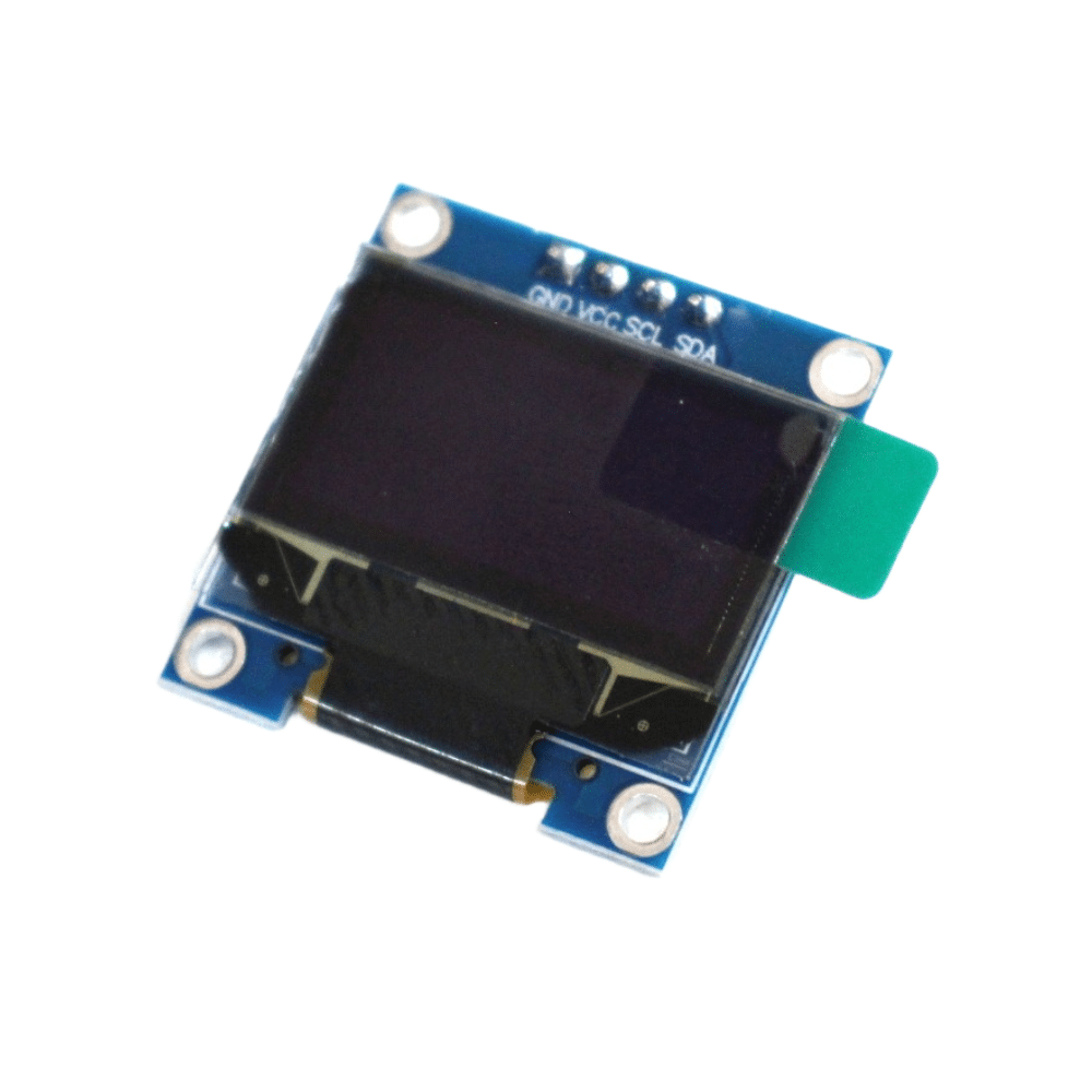
0.96 Inch I2C OLED LCD Module White SSD1306
Add a crisp OLED display to your custom remote to show which device is selected, the current volume level, or the last command sent. 4-pin I2C for easy wiring.
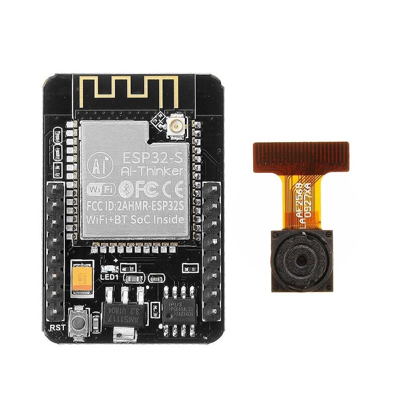
Ai Thinker ESP32 CAM Development Board WiFi+Bluetooth
Build a WiFi-to-IR bridge using this ESP32 board. Control any IR device from your smartphone over WiFi — no line-of-sight needed if you position the IR LED centrally.
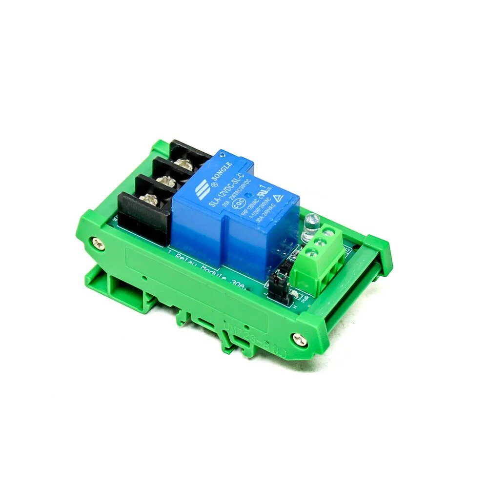
1 Channel 12V 30A Relay Module with Optocoupler
Trigger high-power loads with your IR remote project. Use relay modules to control fans, lights, or pumps based on IR commands received by your Arduino.
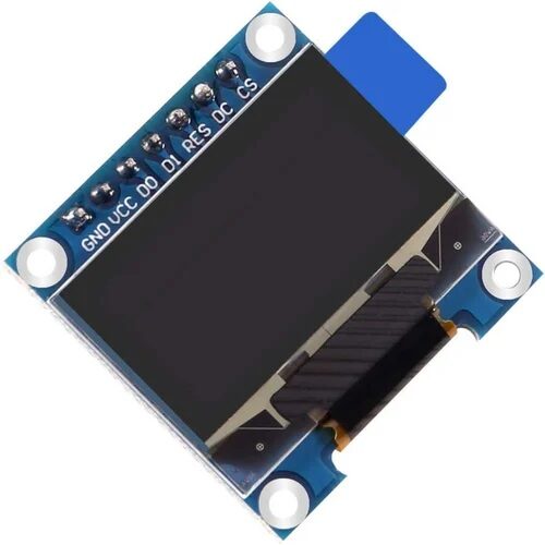
0.96 Inch SPI OLED LCD Module 7pin White SSD1306
SPI variant of the popular OLED display — faster refresh rate for displaying rapidly changing IR command feedback or animated remote UI on your custom remote.
Ai Thinker ESP32-C3-01M Wi-Fi + BLE Module
Ultra-compact ESP32-C3 with WiFi and BLE — build a tiny IR blaster that fits behind your TV and receives commands over BLE from your phone or WiFi from Home Assistant.
Frequently Asked Questions
Q1: My IR LED is transmitting but my TV doesn’t respond. What could be wrong?
Most likely causes: (1) Wrong IR code — use the receiver sketch to capture the exact code from your TV’s original remote, not a generic code list. (2) IR LED not bright enough — add the transistor amplifier circuit for more current. (3) Angle/distance — IR signals are directional; point the LED directly at the TV’s IR sensor (usually on the front bezel). (4) Wrong protocol or carrier frequency — some TVs use 40 kHz (Sony) instead of 38 kHz. Check using the receiver’s protocol printout.
Q2: Can I control an AC unit with this setup?
Yes, but AC remotes are more complex. They transmit the entire AC state (temperature, mode, fan speed, swing) in each button press rather than a simple command code. This results in much longer IR frames. The IRremote library supports many AC protocols (Daikin, Mitsubishi, Panasonic, Voltas, etc.) via the IRac class. Alternatively, record the raw timing data for each AC state and replay it exactly using sendRaw().
Q3: What range can I expect from the IR LED?
A standard 940nm IR LED driven directly from an Arduino pin (~20mA) gives about 2-3 metres range. With the transistor amplifier circuit driving 100mA, expect 8-10 metres — enough for any room. For room-wide coverage, use multiple IR LEDs in parallel through the transistor (3-4 LEDs facing different directions) or use a high-power IR LED rated at 500mA+ with appropriate heatsinking.
Q4: How do I know which buttons on my remote use which protocol?
Use the receiver sketch with IrReceiver.printIRResultShort(&Serial) — it identifies the protocol automatically. Point different buttons at the receiver. Most remotes use a single protocol throughout, but some combination remotes (universal remotes) may switch protocols for different device sections. The IRremote library can identify NEC, Sony, Samsung, Panasonic, RC5, RC6, and dozens of other protocols automatically.
Q5: Can I integrate this with Google Home or Alexa?
Yes! The recommended approach is to use an ESP32 as the IR blaster and run either a Sinric Pro or ESPHome integration. Sinric Pro (free tier available) acts as a bridge between Google/Alexa and your ESP32 via MQTT. When you say “Hey Google, turn off the TV,” Sinric Pro sends the command to your ESP32 which fires the IR LED. This is how many Indian hobbyists build their smart home setups at a fraction of the cost of commercial IR blasters like Broadlink or Sensibo.
Find OLED displays, ESP32 boards, and all the components you need at Zbotic’s Communication & Wireless Modules — India’s go-to store for electronics hobbyists with fast delivery and genuine parts.


Add comment