
GPS doesn’t work indoors — signals are blocked by walls, ceilings, and structural steel. Yet countless applications demand precise indoor location: warehouse robots, hospital asset tracking, smart home occupancy sensing, and robotics competitions. One surprisingly effective and low-cost approach is ultrasonic sensor array trilateration — using multiple HC-SR04 or JSN-SR04T sensors to measure distances from known fixed points and mathematically computing a 2D or 3D position. This guide walks you through the complete theory, hardware setup, calibration, and Arduino implementation of an indoor ultrasonic positioning system.
How Trilateration Works: The Math Made Simple
Trilateration is the process of determining a point’s location by measuring its distance from three or more known reference points. It is different from triangulation, which uses angles. In 2D space, each distance measurement from a fixed sensor defines a circle of possible positions. Two circles intersect at two points. A third circle uniquely resolves which of the two intersection points is the real location (assuming no noise).
Mathematically, if you have three anchor sensors at positions (x₁,y₁), (x₂,y₂), (x₃,y₃) with measured distances d₁, d₂, d₃ to an unknown point (x,y), you solve the system:
(x - x1)² + (y - y1)² = d1²
(x - x2)² + (y - y2)² = d2²
(x - x3)² + (y - y3)² = d3²
Subtracting equation 1 from equations 2 and 3 linearises the system, yielding two linear equations that can be solved by matrix methods or simple substitution. With four or more sensors, a least-squares solution improves accuracy significantly.
Ultrasonic vs Other Indoor Positioning Technologies
| Technology | Typical Accuracy | Cost | Range |
|---|---|---|---|
| Ultrasonic | 2–5 cm | Very Low (₹100–500) | 0.2–4 m |
| UWB | 5–10 cm | High (₹2000+/node) | Up to 50 m |
| Wi-Fi RSSI | 1–3 m | Low | Room-scale |
| BLE Beacons | 1–2 m | Medium | Up to 30 m |
| LiDAR | <1 cm | Very High | Room-scale |
| IR (structured) | 5–10 cm | Medium | Up to 10 m |
Ultrasonic wins on cost for small-room applications where 2–5 cm accuracy is sufficient. It works in dark environments, doesn’t require line-of-sight to beacons (the sound diffracts around some obstacles), and the HC-SR04 is available for under ₹50 in India. The major limitation is multipath reflections from walls, which we’ll address in the calibration section.
Hardware Required and System Architecture
For a basic 2D positioning system covering a 3×3 m room, you need:
- 3+ HC-SR04 ultrasonic sensors (or JSN-SR04T for waterproof/longer range) as anchors, fixed at known positions
- 1 Arduino Mega or Nano with enough digital pins for all sensors
- Tag device: A reflective surface or a second Arduino with a buzzer/ultrasonic transmitter attached to the object being tracked
- Power supply (5 V, capable of 15 mA per sensor)
- Breadboard and jumper wires
The system architecture is: anchors are placed at known (x,y) coordinates in the room corners or walls. The tag (object to track) emits or reflects ultrasonic pulses. Each anchor measures the time-of-flight (ToF) and reports its measured distance over a serial bus or I2C to the master Arduino, which then computes the position using trilateration math.
Placement tip: Place anchors in a non-collinear arrangement — they must not all be on the same line or the trilateration geometry becomes degenerate. A triangular arrangement with one sensor at (0,0), one at (0, 300 cm), and one at (300, 150 cm) works well for a 3×3 m room.
Wiring the Ultrasonic Sensor Array
Each HC-SR04 sensor has four pins: VCC, GND, TRIG, and ECHO. The Arduino Mega is recommended for sensor arrays (three or more sensors) due to its 54 digital pins.
| Sensor | TRIG Pin | ECHO Pin |
|---|---|---|
| Sensor 1 (Anchor A) | D2 | D3 |
| Sensor 2 (Anchor B) | D4 | D5 |
| Sensor 3 (Anchor C) | D6 | D7 |
All VCC pins to the Arduino 5 V rail; all GND pins to common ground. If you power multiple sensors from a single Arduino 5 V pin, ensure the USB current budget is not exceeded — each HC-SR04 draws up to 15 mA. For three sensors, a dedicated 5 V supply is recommended.
Arduino Code: Distance Measurement and Trilateration
The code below measures distances from three anchor sensors and computes the 2D (x,y) position of the tag using linearised trilateration:
// Anchor positions in centimetres
float ax1 = 0,   ay1 = 0;
float ax2 = 0,   ay2 = 300;
float ax3 = 300, ay3 = 150;

const int trigPins[] = {2, 4, 6};
const int echoPins[] = {3, 5, 7};

float measureDistance(int trig, int echo) {
  digitalWrite(trig, LOW);
  delayMicroseconds(2);
  digitalWrite(trig, HIGH);
  delayMicroseconds(10);
  digitalWrite(trig, LOW);
  long duration = pulseIn(echo, HIGH, 30000);
  return duration * 0.01716; // cm (speed of sound 343 m/s at 20°C)
}

void trilaterate(float d1, float d2, float d3, float &px, float &py) {
  // Linearise: subtract equation 1 from 2 and 3
  float A = 2 * (ax2 - ax1);
  float B = 2 * (ay2 - ay1);
  float C = d1*d1 - d2*d2 - ax1*ax1 + ax2*ax2 - ay1*ay1 + ay2*ay2;
  float D = 2 * (ax3 - ax1);
  float E = 2 * (ay3 - ay1);
  float F = d1*d1 - d3*d3 - ax1*ax1 + ax3*ax3 - ay1*ay1 + ay3*ay3;

  float denom = A * E - B * D;
  if (abs(denom) < 0.001) { px = py = -1; return; } // Degenerate
  px = (C * E - B * F) / denom;
  py = (A * F - C * D) / denom;
}

void setup() {
  Serial.begin(115200);
  for (int i = 0; i < 3; i++) {
    pinMode(trigPins[i], OUTPUT);
    pinMode(echoPins[i], INPUT);
  }
}

void loop() {
  float d1 = measureDistance(trigPins[0], echoPins[0]);
  delay(30);
  float d2 = measureDistance(trigPins[1], echoPins[1]);
  delay(30);
  float d3 = measureDistance(trigPins[2], echoPins[2]);
  delay(30);

  float px, py;
  trilaterate(d1, d2, d3, px, py);

  Serial.print("Position: (");
  Serial.print(px, 1);
  Serial.print(", ");
  Serial.print(py, 1);
  Serial.println(") cm");
  delay(100);
}
The 30 ms delays between readings prevent crosstalk — if all sensors fire simultaneously, the sound from sensor 1 can arrive at the ECHO pin of sensor 2, causing false readings. This sequential firing approach sacrifices update rate for reliability. For faster updates, hardware interrupts or a multiplexer approach can be used.
Improving Accuracy: Calibration and Filtering
Raw ultrasonic trilateration typically achieves 5–15 cm accuracy due to temperature effects, multipath reflections, and measurement noise. Here’s how to improve it:
1. Temperature Compensation
The speed of sound is approximately 331.3 + (0.606 × T) m/s where T is temperature in °C. At 25°C (typical Indian room temperature) this is 346.5 m/s, but the HC-SR04’s formula assumes 340 m/s. Add a DHT11 or LM35 temperature sensor and adjust:
float speedOfSound = 331.3 + 0.606 * temperature; // m/s
float distanceCm = (duration / 2.0) * (speedOfSound / 10000.0);
2. Median Filtering
Take 5 readings per sensor per cycle and use the median (not the average) to reject outliers caused by reflections:
float readings[5];
for (int i = 0; i < 5; i++) {
  readings[i] = measureDistance(trig, echo);
  delay(10);
}
// Sort and return middle value
// (implement bubble sort or use a sort library)
3. Kalman Filtering on Position
Apply a simple 1D Kalman filter independently on the estimated X and Y coordinates. This smooths the position estimate over time, reducing jitter from 3–4 cm to under 1 cm for a slowly-moving object.
4. Anchor Position Calibration
Measure anchor positions accurately (within 5 mm) using a tape measure. Errors in anchor placement directly translate to position errors. Consider using a structured calibration: place the tag at 5 known positions around the room and adjust anchor coordinates until the computed positions match.
Limitations and How to Mitigate Them
- Multipath reflections: Sound bounces off walls, causing distance readings 10–30% larger than line-of-sight. Use absorptive foam panels on nearby walls or validate readings statistically.
- Limited range: HC-SR04 works reliably up to 3–4 m. For larger rooms, use JSN-SR04T (waterproof version with 6 m range) or increase sensor count.
- Object detection, not person tracking: Ultrasonic detects the nearest solid surface, not a specific person. A person must carry a reflector or active emitter for reliable tracking.
- Slow update rate: With 3 sensors and 30 ms inter-measurement delays, you get roughly 10 positions per second — sufficient for slow-moving assets but not fast robots.
- No 3D tracking with 3 sensors: You need a minimum of 4 non-coplanar anchors for 3D trilateration.
Extending to 3D Positioning
For 3D positioning (tracking height as well), install a fourth sensor at a different height (e.g., mounted on the ceiling). The math extends naturally — add a third unknown (z) and a fourth equation. Place anchors as follows for a 3×3×3 m room:
- Anchor A: (0, 0, 0) — floor corner
- Anchor B: (300, 0, 0) — floor corner
- Anchor C: (150, 300, 0) — floor centre-back
- Anchor D: (150, 150, 300) — ceiling centre
Solve the 3×3 linear system (after subtracting equation 1 from equations 2, 3, and 4) using Gaussian elimination. This gives centimetre-level 3D positioning using just ₹200 worth of sensors — remarkable for a budget system.
Recommended Products from Zbotic
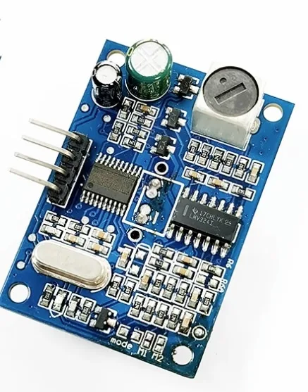
A86 JSN-SR04T Waterproof Ultrasonic Rangefinder Module Version 3.0
The waterproof JSN-SR04T offers up to 6 m range and a separated probe design — perfect as anchor sensors in larger rooms or humid environments where standard HC-SR04 may fail.

LM35 Temperature Sensors
Essential for speed-of-sound temperature compensation. Mount an LM35 near each ultrasonic anchor sensor for accurate local temperature readings and improved positioning accuracy.
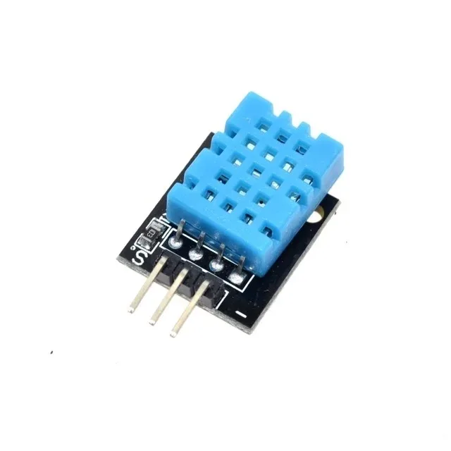
DHT11 Digital Relative Humidity and Temperature Sensor Module
The DHT11 provides both temperature and humidity — humidity also affects ultrasonic wave propagation slightly. Use it for comprehensive environmental compensation in precision systems.
Frequently Asked Questions
Q1: How many sensors do I need for 2D indoor positioning?
A minimum of three non-collinear anchor sensors are needed for 2D trilateration. Three sensors give a unique solution (with some ambiguity in noisy conditions). Adding a fourth anchor allows least-squares optimisation, improving accuracy by 30–50%.
Q2: Can I use HC-SR04 sensors as both transmitter and receiver?
The standard HC-SR04 is a self-contained unit — it transmits a burst, then listens for the echo on the same sensor. For a true time-of-flight system where separate transmitters and receivers are needed (as in active tag systems), use discrete 25 kHz ultrasonic transducers where transmitter and receiver are separate units.
Q3: What is the maximum room size this system supports?
The HC-SR04 has a reliable range of about 4 m. For a 3-sensor system, effective room coverage is roughly 3×3 m. Using JSN-SR04T sensors extends this to about 5×5 m. Beyond that, signal attenuation and reflections degrade accuracy rapidly.
Q4: How do I prevent crosstalk between sensors?
Fire sensors sequentially with at least 30 ms between readings (the time it takes for a 40 kHz echo to decay). Physically point sensors away from each other if possible. For a fully parallel system, use sensors operating at different frequencies (25 kHz vs 40 kHz).
Q5: Can this system track multiple objects simultaneously?
Tracking multiple objects with passive reflectors is difficult because each anchor sensor sees the nearest object. For multi-object tracking, assign each object an active ultrasonic transmitter operating at a distinct time slot (TDMA scheduling) or frequency, then use the anchor sensors as receivers.
Q6: Is there a ready-made library for trilateration on Arduino?
No widely-used dedicated trilateration library exists for Arduino as of 2025. However, the linearised trilateration algorithm shown above is simple enough to implement directly. For Python (Raspberry Pi) implementations, the pylocater and trilat packages exist.
Get all the ultrasonic sensors, temperature modules, and Arduino boards you need from Zbotic’s Sensors & Measurement category. Fast shipping across India, with knowledgeable support for your DIY and robotics projects.


Add comment