
Table of Contents
- What Is the YF-S201 Water Flow Sensor?
- How Does It Measure Flow Rate?
- Technical Specifications
- Wiring YF-S201 to Arduino
- Arduino Code for Flow Rate and Volume
- Calibration: Getting Accurate Readings
- Project Ideas
- Limitations and Alternatives
- Frequently Asked Questions
- Conclusion
Water is one of our most precious and expensive resources. Whether you are building an automatic irrigation controller, a home water meter, or an industrial fluid monitoring system, measuring water flow accurately is fundamental. The YF-S201 water flow sensor is a Hall-effect based turbine flow meter that works seamlessly with Arduino, making it the most popular choice for hobbyist and semi-professional water measurement projects. At under ₹300, it is affordable enough for DIY automation yet capable enough for meaningful flow rate and volume measurement. This guide walks you through everything — hardware, code, calibration, and applications.
What Is the YF-S201 Water Flow Sensor?
The YF-S201 is a 1/2-inch (DN15) threaded inline water flow sensor. It contains a rotor fitted with a small magnet and a Hall-effect sensor. As water flows through the sensor body, it spins the rotor. The spinning magnet triggers the Hall-effect sensor, which outputs one pulse per revolution. By counting pulses per unit time, you can calculate the flow rate in litres per minute (L/min). By accumulating pulses, you can calculate total volume in litres.
The sensor has a 1/2-inch BSP (or G1/2) threaded inlet and outlet, making it directly compatible with standard plumbing fittings, irrigation tubing, and water pump lines commonly used in Indian households and agriculture. It is widely used in:
- Automated irrigation and drip watering systems
- Home water consumption monitoring
- Water purifier (RO) inlet and outlet monitoring
- Aquarium and fish tank water management
- Industrial cooling water loop monitoring
- Coffee machines and beverage dispensing systems
How Does It Measure Flow Rate?
The YF-S201 operates on the Hall-effect turbine principle. Inside the plastic housing sits a small rotor (impeller) with curved vanes. When water flows through the body, it pushes against the vanes and spins the rotor. A small permanent magnet embedded in the rotor spins past a Hall-effect sensor (typically a US5881 or similar) mounted in the sensor body.
Each complete rotation of the rotor generates one Hall-effect pulse. The datasheet specifies the frequency factor (K-factor) as approximately 7.5 pulses per litre. This means for every 7.5 pulses counted, exactly 1 litre of water has passed through the sensor. In terms of flow rate:
- Flow Rate (L/min) = Pulse Frequency (Hz) / 7.5
- Volume (Litres) = Total Pulse Count / 7.5
The Arduino counts these pulses using an interrupt on a digital pin, which is critical — using polling in the main loop would miss many pulses, especially at higher flow rates, leading to significant measurement error.
Technical Specifications
| Parameter | Value |
|---|---|
| Working Voltage | 5V DC (4.5V – 18V range) |
| Maximum Current | 15 mA at 5V |
| Flow Rate Range | 1 – 30 L/min |
| Load Capacity | ≤ 10 mA (output signal) |
| Operating Pressure | ≤ 1.75 MPa (17.5 bar) |
| Water Temperature | 0°C – 80°C |
| Thread Size | G1/2″ (BSP 1/2″) |
| Output Signal | Square wave (Hall effect) |
| Pulse Rate (K-factor) | ~7.5 pulses per litre |
| Accuracy | ±3% at rated flow |
| Cable Length | 15 cm (3-wire: Red, Black, Yellow) |
Wire colors: Red = VCC (5V), Black = GND, Yellow = Signal output
Wiring YF-S201 to Arduino
The YF-S201 has only three wires, making it one of the simplest sensors to connect:
| YF-S201 Wire | Arduino Pin | Notes |
|---|---|---|
| Red (VCC) | 5V | Power supply |
| Black (GND) | GND | Ground |
| Yellow (Signal) | D2 | Interrupt pin (D2 or D3 on Uno) |
Add a 10kΩ pull-up resistor between the Yellow signal wire and 5V. Although the sensor has an internal pull-up, an external one ensures clean signal edges and prevents false pulses from electrical noise, especially in environments with pump motors running nearby.
Arduino Code for Flow Rate and Volume
This is a complete, production-quality sketch for measuring flow rate and cumulative volume with the YF-S201:
#include <Arduino.h>

#define FLOW_SENSOR_PIN 2

volatile unsigned long pulseCount = 0;
float flowRate = 0.0;
float volumeLitres = 0.0;
unsigned long totalPulseCount = 0;
unsigned long previousTime = 0;
const float PULSES_PER_LITRE = 7.5;

void IRAM_ATTR pulseCounter() {
  pulseCount++;
}

void setup() {
  Serial.begin(9600);
  pinMode(FLOW_SENSOR_PIN, INPUT_PULLUP);
  attachInterrupt(digitalPinToInterrupt(FLOW_SENSOR_PIN), pulseCounter, RISING);
  previousTime = millis();
  Serial.println("YF-S201 Water Flow Sensor Ready");
  Serial.println("Flow Rate (L/min) | Volume (L)");
}

void loop() {
  unsigned long currentTime = millis();
  unsigned long elapsedTime = currentTime - previousTime;

  if (elapsedTime >= 1000) { // Calculate every second
    // Disable interrupt to safely read pulseCount
    detachInterrupt(digitalPinToInterrupt(FLOW_SENSOR_PIN));

    unsigned long pulses = pulseCount;
    pulseCount = 0;
    totalPulseCount += pulses;

    // Re-enable interrupt
    attachInterrupt(digitalPinToInterrupt(FLOW_SENSOR_PIN), pulseCounter, RISING);

    // Calculate flow rate in L/min
    // Pulses per second / 7.5 = L/min ... but per second means:
    // (pulses / elapsed_seconds) / 7.5 * 60 ... simplified:
    float elapsedSeconds = elapsedTime / 1000.0;
    flowRate = (pulses / elapsedSeconds) / PULSES_PER_LITRE * 60.0;

    // Cumulative volume
    volumeLitres = totalPulseCount / PULSES_PER_LITRE;

    Serial.print(flowRate, 2);
    Serial.print(" L/min  |  ");
    Serial.print(volumeLitres, 3);
    Serial.println(" L");

    previousTime = currentTime;
  }
}
Open the Serial Monitor at 9600 baud and you will see live flow rate and accumulated volume updated every second. The detachInterrupt / attachInterrupt pattern ensures atomic read of the volatile pulseCount variable without race conditions.
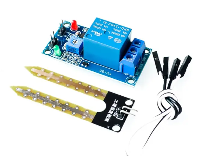
5V/12V Soil Moisture Sensor Relay Control Module
Combine with the YF-S201 flow sensor to build a smart irrigation system that measures both soil moisture and water delivery volume for precision farming.
Calibration: Getting Accurate Readings
The 7.5 pulses/litre K-factor is a nominal value. Your specific sensor unit may vary due to manufacturing tolerances, water pressure, temperature, and installation orientation. For maximum accuracy, calibrate your sensor with a known volume:
- Connect the sensor in your system and run the code above
- Reset the total volume counter to zero
- Flow exactly 1 litre of water through the sensor (measured with a calibrated measuring container)
- Note the total pulse count displayed on Serial Monitor
- Update
PULSES_PER_LITREin the code to this measured value
For example, if you counted 743 pulses for 1 litre, your corrected K-factor is 7.43. After this one-time calibration, the sensor typically achieves ±1-2% accuracy in the middle of its flow range.
Calibration tips:
- Calibrate at the expected operational flow rate, not at extremes
- Install the sensor with at least 10 pipe diameters of straight pipe upstream to avoid turbulence effects on accuracy
- Vertical upward flow orientation typically gives the most consistent readings
- Use Teflon tape on all pipe threads to prevent leaks without affecting sensor accuracy
Project Ideas
1. Smart Irrigation Controller
Combine the YF-S201 with a soil moisture sensor and relay-controlled water pump. The system opens the valve when soil is dry and closes it after delivering a precisely measured volume — no over-watering, no wasted water. Add a DS3231 RTC to schedule watering windows.
2. Household Water Budget Monitor
Install on your main water inlet pipe. Log daily, weekly, and monthly consumption to an SD card or ESP8266 Wi-Fi module. Display real-time usage on an LCD, and send SMS alerts when the daily budget is exceeded using a GSM module.
3. RO Water Purifier Monitor
Mount one sensor on the RO input and one on the purified water output. Calculate rejection ratio (waste water to purified water ratio). Alert via buzzer or LED when the membrane efficiency drops below threshold — a useful maintenance indicator.
4. Aquarium Auto Top-Off System
Evaporation in aquariums reduces water level and increases salinity in saltwater tanks. Use a float switch to trigger a pump and the YF-S201 to measure exactly how much freshwater was added, maintaining precise salinity levels.
5. Beverage Dispenser Volume Control
Install on juice, milk, or beverage dispensing equipment. Program precise serving volumes (100ml, 200ml, 500ml) and automatically stop the pump when the target volume is dispensed — reproducible portions every time.
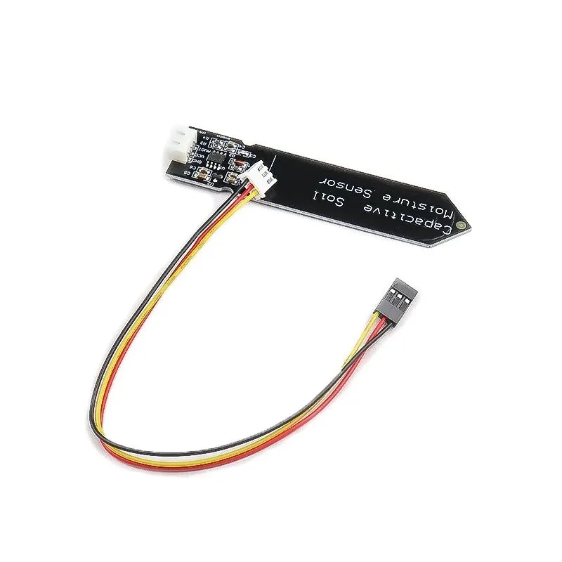
Capacitive Soil Moisture Sensor
The ideal partner for your YF-S201 irrigation project — this corrosion-resistant capacitive sensor gives reliable soil moisture readings without degrading over time.
Limitations and Alternatives
The YF-S201 is an excellent entry-level flow sensor, but it has real limitations you should be aware of:
- Accuracy: ±3% at rated flow — suitable for automation but not for billing or scientific measurement
- Flow range: Unreliable below 1 L/min and above 30 L/min
- Liquid type: Designed for clean water only — sediment, chemicals, or viscous fluids damage the rotor
- Temperature: Limited to 80°C — not suitable for hot steam or very hot water
- Pressure: Max 1.75 MPa — suitable for most residential plumbing but not high-pressure industrial lines
For higher accuracy applications, consider ultrasonic flow meters (non-invasive, clamp-on) or Coriolis flow meters. For very low flow rates (drops/minute), a peristaltic pump with encoder or a liquid-level differential sensor may be more appropriate.
Frequently Asked Questions
Can the YF-S201 measure flow in both directions?
No. The turbine spins in one direction only. Reverse flow simply spins the rotor in reverse, and no pulses are generated. The sensor is a unidirectional device only.
What is the minimum flow rate the YF-S201 can detect?
The sensor starts generating pulses at approximately 0.5–1 L/min, but measurement accuracy below 1 L/min is poor. At very low flow rates, the rotor may stick or not spin consistently.
Can I use the YF-S201 with ESP32 or Raspberry Pi?
Yes. On ESP32, use GPIO interrupt pins and the attachInterrupt() function exactly as with Arduino. On Raspberry Pi, use the RPi.GPIO library with edge-detection callbacks. Both are very popular platforms for this sensor.
Is the YF-S201 waterproof?
The sensor body is sealed and water-tight when properly threaded into fittings, but the cable and electronics are not waterproof. Protect the cable entry point with self-amalgamating tape or silicone sealant if used in wet environments.
Why are my readings erratic or jumping?
Usually caused by electrical noise from nearby pump motors or relay switching. Add a 10kΩ pull-up resistor to the signal line, route the sensor cable away from power cables, and add a small 100nF capacitor between signal and ground near the Arduino pin for noise filtering.
How do I convert L/min to gallons per minute?
Multiply by 0.2642. So 10 L/min = 2.642 GPM. For liters to gallons total volume, multiply litres by 0.2642 as well.
Conclusion
The YF-S201 water flow sensor is an incredibly accessible tool for measuring water consumption, flow rate, and volume in Arduino projects. With just three wires, a single interrupt pin, and a short sketch, you can have a fully functional flow meter running in minutes. Calibrate it once with a known volume, and you will achieve ±1-2% accuracy — good enough for irrigation automation, consumption monitoring, and volume-controlled dispensing.
The key to reliable readings is always using hardware interrupts (not polling), adding a pull-up resistor, and installing the sensor in a location with at least 10 diameters of straight upstream pipe. Once you get it working, the project possibilities are endless: from smart farms to water budgeting to industrial fluid management.
From soil moisture sensors to ultrasonic rangefinders, Zbotic has everything you need to build complete water management automation projects. Explore sensors at Zbotic →


Add comment