
Whether you are powering a microcontroller, a motor driver, or a sensitive analog circuit, choosing the right voltage regulator can make or break your project. Voltage regulators are among the most fundamental building blocks in electronics, yet the decision between a linear regulator and a switching regulator confuses beginners and intermediate makers alike. This comprehensive guide covers every aspect of voltage regulator types — how they work, their advantages and drawbacks, when to use which, and practical design tips for hobbyists and professionals in India.
What Is a Voltage Regulator?
A voltage regulator is an electronic circuit or integrated circuit (IC) that maintains a constant output voltage regardless of changes in input voltage or load current. In real-world power systems, the voltage from batteries, adapters, or the mains supply varies due to load fluctuations, temperature changes, and supply quality. A voltage regulator ensures your circuit always receives a stable, predictable voltage.
Voltage regulators are broadly classified into two families:
- Linear regulators — dissipate excess voltage as heat
- Switching regulators (SMPS) — convert power by rapidly switching transistors on and off
Both families have sub-types optimised for specific applications. Understanding the underlying physics of each type helps you make the correct engineering decision at the design stage.
Linear Voltage Regulators
Linear regulators work by placing a variable resistive element — typically a power transistor — in series between the input and output. The transistor continuously adjusts its resistance so that the voltage drop across it equals the difference between input and output voltage (Vin − Vout). The result is a clean, low-noise output.
How a Linear Regulator Works
Inside a linear regulator, an error amplifier compares the output voltage (sampled through a resistor divider) with an internal precision voltage reference (bandgap reference). If the output drops, the error amp reduces the series transistor’s resistance, allowing more current through. If the output rises, it increases resistance, restricting current. This negative feedback loop happens continuously, providing excellent line and load regulation.
Common Linear Regulator ICs
- 78xx series (e.g., LM7805, LM7812): Fixed positive voltage output regulators; LM7805 gives +5 V and is the most popular IC in hobbyist electronics worldwide.
- 79xx series (e.g., LM7905, LM7912): Fixed negative voltage output regulators used in op-amp dual-supply circuits.
- LM317: Adjustable positive output regulator, output set by two external resistors (Vout = 1.25 × (1 + R2/R1)).
- LM337: Adjustable negative output version of LM317.
- LM723: Precision voltage regulator with current limiting for laboratory power supplies.
Advantages of Linear Regulators
- Extremely low output noise and ripple (ideal for audio and RF circuits)
- Simple circuit — typically need only 2–3 external capacitors
- Fast transient response
- No electromagnetic interference (EMI)
- Very low cost and widely available
- Easy to design and debug
Disadvantages of Linear Regulators
- Efficiency is limited: η = Vout / Vin (e.g., 5 V from 12 V gives only 41.7% efficiency)
- Waste power is dissipated as heat — requires heatsinking for high-current applications
- Can only step down voltage (buck operation only)
- Dropout voltage limits minimum Vin − Vout gap (standard: ~2–3 V)
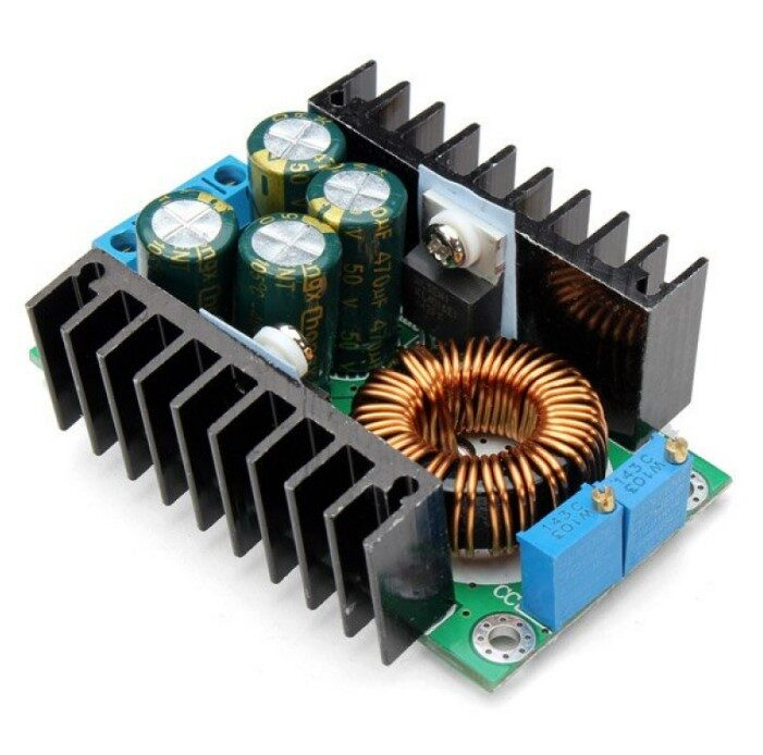
300W 10A DC-DC Step-down Buck Converter Adjustable Constant Voltage Module
A high-efficiency switching buck converter for projects demanding up to 10A output current — far beyond the capability of any linear regulator without massive heatsinking.
Switching Voltage Regulators
Switching regulators (also called switch-mode power supplies or SMPS) operate on an entirely different principle. Instead of dissipating excess energy as heat, they use rapid on/off switching of a transistor (MOSFET or BJT) combined with energy-storage elements (inductors and capacitors) to transfer power efficiently from input to output.
How a Switching Regulator Works
The control IC drives a power switch at high frequency (typically 50 kHz to 2 MHz). During the ON phase, energy is stored in an inductor. During the OFF phase, the inductor releases stored energy to the output. A feedback loop monitors output voltage and adjusts the duty cycle (ratio of ON time to total period) via pulse-width modulation (PWM) to maintain regulation. Because the switch is either fully ON or fully OFF, power loss is minimised.
Common Switching Regulator ICs and Modules
- LM2596: Popular 3A buck converter IC, available in adjustable and fixed versions (3.3 V, 5 V, 12 V)
- XL4016: High-current 8A buck converter used in ready-made modules
- MT3608: Boost converter IC for stepping up voltage (e.g., 3.7 V to 5 V)
- XL6009: Boost/buck-boost converter up to 4A
- LT1073: Micro-power boost converter for battery-powered devices
Advantages of Switching Regulators
- High efficiency: typically 80–95% regardless of Vin/Vout ratio
- Can step up (boost), step down (buck), or invert voltage
- Minimal heat generation — small form factor possible
- Handles much higher output currents without large heatsinks
- Suitable for battery-powered projects where efficiency directly extends run time
Disadvantages of Switching Regulators
- Output has switching noise and ripple (requires careful filtering)
- More complex circuit design — inductor selection, layout, and stability are critical
- Generates EMI that can disturb nearby radio receivers and sensitive analog circuits
- Slower transient response compared to linear regulators
- Higher cost for the IC and external components
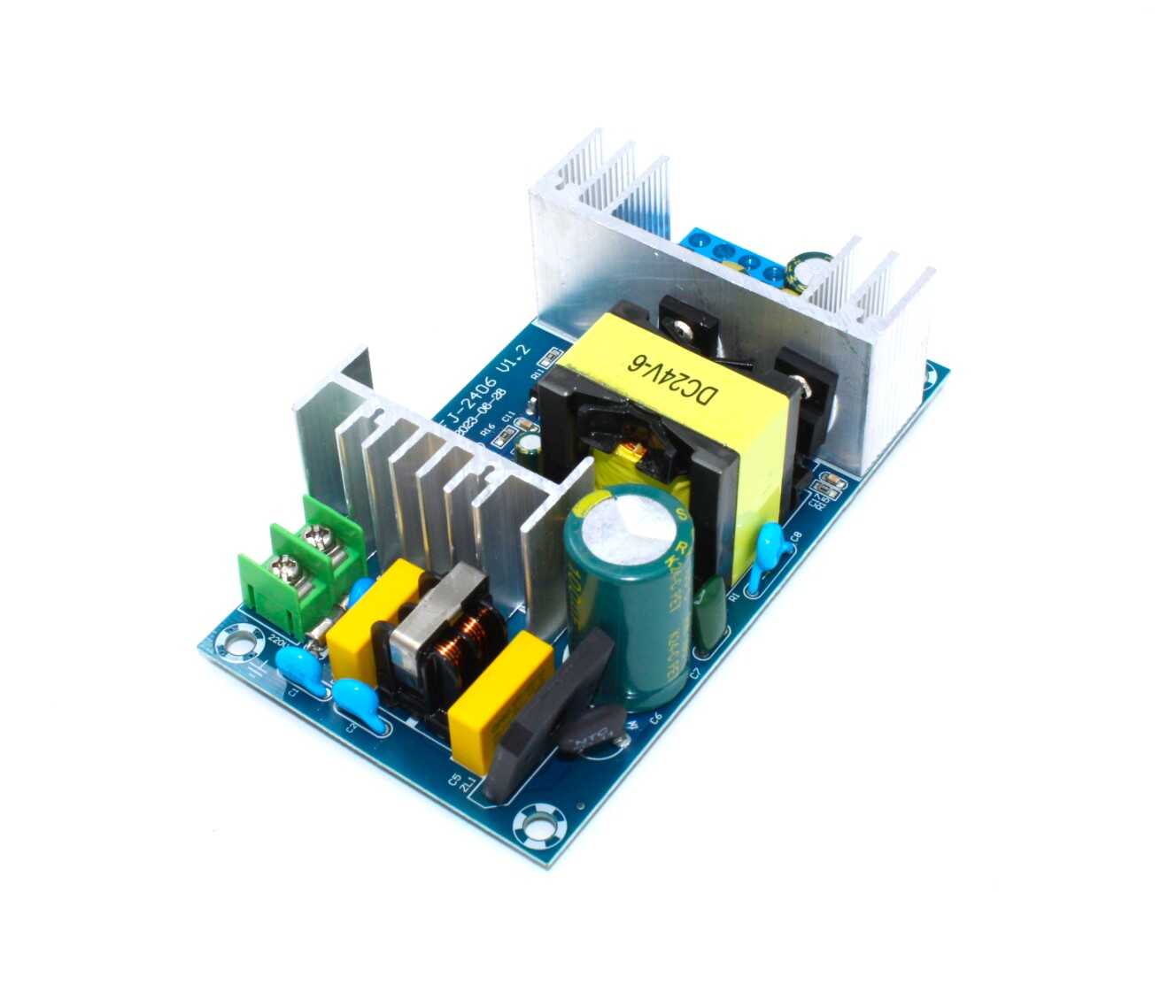
150W AC-DC Buck Converter 100V–240V to 24V 6A–9A Step Down Power Supply Module
Converts Indian mains AC directly to regulated 24V DC at up to 9A — a complete switching power supply module ideal for industrial and automation projects.
Linear vs Switching: Head-to-Head Comparison
| Parameter | Linear Regulator | Switching Regulator |
|---|---|---|
| Efficiency | Low (depends on Vin/Vout ratio) | High (80–95%) |
| Output Noise | Very low | Moderate (needs filtering) |
| Cost | Low | Moderate to high |
| Complexity | Simple | Complex |
| Conversion Type | Step-down only | Step-down, step-up, invert |
| EMI | None | Significant |
| Transient Response | Fast | Slower |
| Heat Dissipation | High (requires heatsink) | Low |
| Minimum Vin–Vout | ~2–3 V (standard), ~0.1 V (LDO) | Depends on topology |
Low-Dropout (LDO) Regulators
A special class of linear regulator worth understanding separately is the Low-Dropout (LDO) regulator. Standard linear regulators require Vin to be at least 2–3 V above Vout. LDOs reduce this “dropout voltage” to as little as 0.1–0.5 V by using a PMOS or PNP pass transistor instead of an NPN Darlington configuration.
LDOs are critical in battery-powered designs. For example, powering an ESP32 at 3.3 V from two AA batteries (nominal 3.0 V) is only possible with an LDO — a standard regulator would shut down because Vin is below its dropout voltage. Popular LDOs include the AMS1117-3.3, MIC5205, LP2950, and TPS7A47.
LDOs are also preferred in post-regulation stages after a switching supply — the switcher handles efficiency; the LDO cleans up the noise. This two-stage approach gives you the best of both worlds: the efficiency of switching and the noise performance of linear regulation.
Buck, Boost, Buck-Boost and Flyback Topologies
Switching regulators come in several topologies, each suited to a different conversion requirement:
Buck Converter (Step-Down)
The most common topology. The switch and inductor form an energy-transfer network. Output voltage is always less than input voltage. Duty cycle D = Vout / Vin (in ideal case). Used in most DC-DC modules available on the market and in battery chargers, LED drivers, and microcontroller power supplies.
Boost Converter (Step-Up)
Energy stored in the inductor during the ON phase is added to the input voltage during the OFF phase, producing an output higher than input. Used to step up a single Li-ion cell (3.7 V) to 5 V for USB power banks, or 12 V to 24 V for motor drives.
Buck-Boost Converter
Combines both topologies. Output voltage can be either higher or lower than input, making it ideal for systems where the supply voltage fluctuates across the desired output (e.g., a Li-ion battery discharging from 4.2 V to 3.0 V powering a 3.3 V circuit). Output is typically inverted in polarity in the basic topology (SEPIC and Cuk converters are non-inverting alternatives).
Flyback Converter
An isolated topology using a transformer. Input and output share no common ground, enabling galvanic isolation, multiple output rails, and mains-to-low-DC conversion. Used in phone chargers, AC adapters, and industrial power supplies. More complex but essential when isolation is required (e.g., medical devices, high-voltage systems).
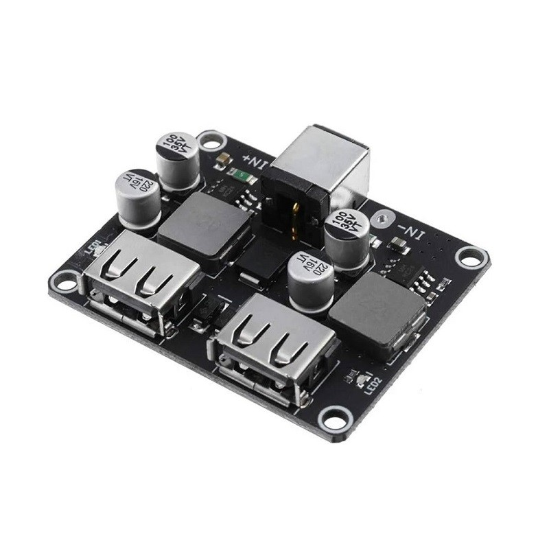
2 Channel USB QC3.0 QC2.0 DC-DC Buck Converter Charging Step Down Module
A ready-to-use buck converter module with dual QC3.0 USB ports — perfect for building your own fast-charging power bank or lab USB supply from a 6–32V source.
Efficiency, Heat Dissipation and Thermal Management
The efficiency equation for a linear regulator is simply η = Vout / Vin. If you use an LM7805 (5 V out) from a 12 V input, efficiency is 5/12 = 41.7%. The remaining 58.3% is converted to heat in the package. At 1A load, that is 7 W of heat — enough to burn fingers and require a large heatsink.
The heat that must be dissipated is: P_heat = (Vin − Vout) × Iout. For 12 V → 5 V at 2A, P_heat = 7 × 2 = 14 W. This requires a proper aluminium heatsink with thermal paste and possibly forced air cooling.
Switching regulators are rated by their efficiency curve. A good buck module achieves 92% at medium load. At 12 V → 5 V, 2A with 92% efficiency, only 0.87 W is lost as heat — no heatsink needed in most cases. This is why switching regulators dominate in any high-current, battery-powered, or thermally constrained design.
Thermal resistance matters: The TO-220 package of LM7805 has θ_JA ≈ 50°C/W without heatsink. At 7 W dissipation, junction temperature rises 350°C above ambient — impossible without a heatsink. Always calculate thermal budgets before finalising a linear regulator design.
Noise, Ripple and Sensitive Circuits
Linear regulators produce output noise in the microvolts range — typically 10–100 µV RMS. This makes them the default choice for:
- ADC reference voltage supply (noise directly affects conversion accuracy)
- RF PLL and VCO power rails (noise causes phase noise and spurious emissions)
- Audio preamplifier and DAC power supply
- Precision op-amp circuits
- Sensor signal conditioning
Switching regulators produce output ripple typically between 10–100 mV peak-to-peak at the switching frequency. While output capacitors and LC filters reduce this, reaching the noise floor of a linear regulator is difficult. For mixed-signal designs, the recommended approach is to use an SMPS for the digital section and an LDO for the analog section, with separate ground planes.
EMI from switching regulators can also couple into nearby circuits through PCB traces, power planes, and radiated fields. Proper layout — short, wide switching loops, ground pour, and filter inductors — is essential for regulatory compliance (BIS certification in India requires conducted and radiated emissions testing).
How to Choose the Right Regulator for Your Project
Use this framework to select the correct voltage regulator type:
Choose a Linear Regulator When:
- Vin and Vout are close (dropout ≤ 3 V) and current is under 500 mA
- The circuit is noise-sensitive (RF, audio, ADC, sensors)
- You need the simplest possible design with minimal components
- EMI must be minimised (medical devices, radio transceivers)
- The power budget allows for heat dissipation losses
Choose a Switching Regulator When:
- Output current exceeds 500 mA or input-output voltage difference is large
- Running from a battery and efficiency is critical for runtime
- You need to step up voltage (boost) or invert it
- Thermal management is constrained (no space for heatsink)
- Multiple output voltages are needed from one input
Use Both (Post-Regulation):
- Put an SMPS first for efficiency, then an LDO to clean noise for sensitive analog sections
- Common in mixed-signal designs: DSP + ADC + RF front-end on one board
Practical Circuit Examples
LM7805 Classic 5V Linear Supply
Connect a 1000 µF electrolytic capacitor from Vin to GND and a 100 nF ceramic capacitor from Vout to GND. The input capacitor filters ripple from the unregulated supply; the output capacitor improves transient response and stability. Mount the LM7805 on a heatsink if load current exceeds 300 mA. Always check that Vin ≥ 7.5 V (accounting for 2.5 V dropout at full load).
LM317 Adjustable Regulator
Use R1 = 240 Ω (from ADJ to output) and R2 = adjustable resistor to set voltage. Formula: Vout = 1.25 × (1 + R2/R1). For 3.3 V, R2 ≈ 392 Ω. Add a 10 µF bypass cap across R2 to improve ripple rejection.
Ready-Made Buck Module
Zbotic’s DC-DC buck converter modules accept a wide input range (4–40 V) and produce adjustable output voltage. Simply connect Vin, GND, and adjust the onboard potentiometer while measuring Vout with a multimeter. These modules are ideal for quick prototyping and eliminate the need to source inductors, MOSFETs, and control ICs separately.
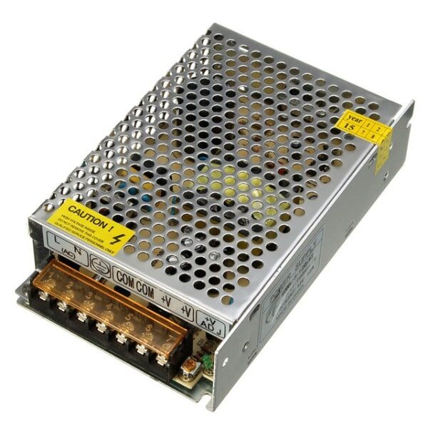
12V 10A SMPS – 120W DC Metal Power Supply
A regulated 12V 10A switching power supply for benchtop use, LED strips, and automation projects — delivers clean regulated DC from Indian 230V mains supply.
Frequently Asked Questions
Q1: Can I use an LM7805 to power an Arduino Uno?
Yes. The Arduino Uno requires 5V and typically draws 50–200 mA. An LM7805 with a 9V or 12V input and a heatsink handles this easily. However, if you are powering the Arduino from a 9V battery and battery life matters, use a buck converter instead — the linear regulator wastes over 44% of your battery energy as heat.
Q2: What is the dropout voltage and why does it matter?
Dropout voltage is the minimum difference between Vin and Vout required for regulation. Standard LM78xx regulators need at least 2–2.5 V of headroom. LDO regulators need as little as 0.1–0.5 V. If Vin drops below (Vout + dropout), the output also drops and regulation is lost. This is critical when running from batteries that discharge over time.
Q3: Why does my switching regulator output have ripple?
Switching ripple is an inherent characteristic of SMPS topologies. The output voltage oscillates at the switching frequency (e.g., 50 kHz–1 MHz). Increase output capacitance, use low-ESR capacitors (polymer or MLCC), add a small series inductor (LC post-filter), and ensure good PCB layout to minimise ripple. Typical ripple for a well-designed module is 20–50 mV.
Q4: Is it safe to connect a linear and switching regulator in parallel?
No. Never parallel two voltage regulators without current sharing circuitry. Regulators will fight each other as their output voltages differ slightly. The correct approach is cascading: switching regulator first (for efficiency), followed by a linear LDO (for noise filtering) in series.
Q5: What voltage regulator is used in a phone charger?
Modern phone chargers use a flyback switching topology to convert 100–240 V AC to 5 V or 9 V DC. Inside the flyback circuit, a primary-side controller drives a high-voltage MOSFET, a transformer isolates the output, and a secondary-side synchronous rectifier and LDO provide the final regulated output. This gives safety isolation from mains and high efficiency in a compact form factor.
Q6: Can I build my own switching regulator, or should I use a module?
For prototyping and learning, use ready-made modules from Zbotic. They include all components (inductor, capacitors, MOSFET, control IC) pre-assembled and tested. Custom PCB designs make sense for production where space, cost, and performance are tightly optimised. Building your first switching regulator from scratch requires careful inductor selection, layout knowledge, and an oscilloscope for debugging.
Whether you need a simple LM7805 for your first circuit or a high-efficiency 300W buck converter for a serious build, Zbotic has all the power components you need — shipped fast across India.


Add comment