
Under-Voltage Lockout (UVLO): Battery Protection Circuit Guide
An under voltage lockout (UVLO) circuit is one of the most important protection mechanisms you can add to any battery-powered project. Whether you’re building a portable Arduino gadget, a LiPo-powered drone controller, or a solar-charged sensor node, UVLO ensures your circuit shuts down gracefully before the battery voltage drops too low — preventing irreversible cell damage and data corruption. In this guide, we’ll cover how UVLO works, how to design one from scratch, and which ICs make the job easy.
What Is Under-Voltage Lockout?
Under-Voltage Lockout (UVLO) is a protection feature that disables a power converter, load circuit, or entire system when the input supply voltage drops below a defined threshold. Once the voltage falls below this trip point, the circuit cuts off power to the load — preventing the battery from being over-discharged.
UVLO is found as an integrated feature in many switching regulators, microcontroller supervisors, and battery management ICs. But it can also be built discretely using a comparator, a voltage reference, and a few passive components — making it accessible to Indian hobbyists and makers working on a budget.
The key parameters of any UVLO circuit are:
- VUVLO_FALL — the voltage at which the output turns OFF (discharge threshold)
- VUVLO_RISE — the voltage at which the output turns back ON (recovery threshold)
- Hysteresis — the difference between rise and fall thresholds; prevents rapid switching near the trip point
Why UVLO Matters for Battery-Powered Projects
Deep discharge is the number one killer of rechargeable batteries. Here’s why UVLO is non-negotiable:
LiPo and Li-ion Battery Safety
Lithium cells should never be discharged below 3.0V per cell. Below this voltage, copper dissolution occurs inside the cell, permanently degrading capacity. A single over-discharge event can reduce a LiPo pack’s usable capacity by 20–40%. In extreme cases, it causes internal short circuits that are a fire hazard. A UVLO circuit set at 3.2V/cell gives a comfortable safety margin.
Lead-Acid Battery Longevity
12V sealed lead-acid (SLA) batteries — common in solar projects and backup UPS circuits — suffer irreversible sulfation when discharged below 10.5V (equivalent to 1.75V/cell). A UVLO set to cut off at 11.0V can triple the usable battery lifespan.
System Stability
Microcontrollers operating below their minimum supply voltage behave unpredictably. Flash memory writes may corrupt at brown-out conditions. A UVLO ensures the MCU either operates correctly or is held in reset — never in an undefined state that could corrupt EEPROM data or trigger unintended actuator movement.
Regulatory Compliance
Consumer electronics sold in India (BIS-certified products) are often required to demonstrate safe battery management. UVLO is a fundamental part of any BMS that meets IEC 62133 battery safety standards.
How UVLO Works: The Circuit Explained
The simplest discrete UVLO uses a comparator (like the LM393 or LM741) to compare the battery voltage (divided down by a resistor divider) against a stable voltage reference.
Here is the basic operating principle:
- A resistor voltage divider samples the battery voltage and scales it to the comparator’s input range
- The comparator’s other input is connected to a fixed voltage reference (e.g., 1.25V from a TL431 or 2.5V from a REF02)
- When the divided battery voltage exceeds the reference, the comparator output is HIGH → load is enabled
- When battery voltage drops and the divided voltage falls below the reference, comparator output goes LOW → load is disabled via a P-channel MOSFET or enable pin
The load switching element is typically a P-channel MOSFET (e.g., IRF9540 or AO3407) whose gate is controlled by the comparator output. When the comparator output is high, the MOSFET turns off. When the comparator output is low (open-drain), the MOSFET gate is pulled to ground and turns on — connecting the battery to the load.

0 Ohm 0.25W Carbon Film Resistor (Pack of 100)
Essential for breadboard jumper connections and zero-ohm links in UVLO prototype circuits. Pack of 100 gives you plenty for experimentation.
Setting the UVLO Threshold: Resistor Divider Calculation
The most critical part of designing a UVLO is setting the correct threshold voltage. Here’s how to calculate the resistor divider values.
For a Single LiPo Cell (4.2V full, 3.0V cutoff)
We want VUVLO_FALL = 3.2V. Our comparator reference voltage VREF = 1.25V (TL431 default).
The voltage divider equation:
VREF = VBATT × R2 / (R1 + R2)
Rearranging:
R1/R2 = (VBATT / VREF) – 1 = (3.2 / 1.25) – 1 = 1.56
Choose standard values: R2 = 10kΩ, R1 = 15kΩ (gives ratio 1.5, sets threshold at ~3.125V — acceptable). For tighter accuracy, use R1 = 10kΩ + 5.6kΩ in series.
Important: Use 1% tolerance metal film resistors for accurate thresholds. Carbon film resistors have ±5% tolerance, which introduces up to ±160mV error on a 3.2V threshold — too much for LiPo protection.
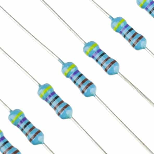
1.5 Ohm 1/4W Metal Film Resistor MFR (Pack of 100)
1% tolerance metal film resistors are critical for accurate UVLO threshold setting. Much more precise than carbon film types for voltage divider networks.
For a 12V Lead-Acid Battery
Set VUVLO_FALL = 11.0V, VREF = 2.5V (REF02 or TL431 adjusted).
R1/R2 = (11.0 / 2.5) – 1 = 3.4
Choose: R2 = 10kΩ, R1 = 33kΩ (ratio 3.3, threshold ≈ 10.75V — adjust R1 to 34kΩ for closer match).
Popular UVLO ICs and Supervisors
While discrete UVLO circuits work well, dedicated ICs offer better accuracy, lower component count, and integrated features like reset delay timers.
TL431 — Programmable Shunt Reference
The TL431 is a 3-terminal adjustable shunt regulator with a 2.5V internal reference. It’s commonly used as a comparator/reference for UVLO circuits. Available in SOT-23 and TO-92 packages. Cost: ₹5–15 each in India.
LM393 — Dual Comparator
A general-purpose dual voltage comparator, perfect for building custom UVLO with hysteresis. Open-collector output makes it easy to drive MOSFET gates. Cost: ₹8–20 each.
MCP100 / MCP130 — Microchip Supervisors
Dedicated voltage supervisors with factory-set thresholds (2.3V to 4.6V available). Assert a RESET or ENABLE signal when voltage drops below the set point. Include built-in hysteresis and are available in tiny SOT-23 packages.
Texas Instruments TPS3840 Series
Modern nanopower supervisors with UVLO thresholds from 0.4V to 5.0V. Supply current as low as 340nA — ideal for ultra-low-power IoT nodes where the UVLO circuit itself must not drain the battery.
Integrated UVLO in Buck Converters
Many SMPS controllers (like MP2307, XL4016, LM2596) include built-in UVLO that cuts off when input voltage drops below 4.5–7V. However, these protect the converter, not the battery — they don’t account for battery chemistry-specific cutoff voltages.
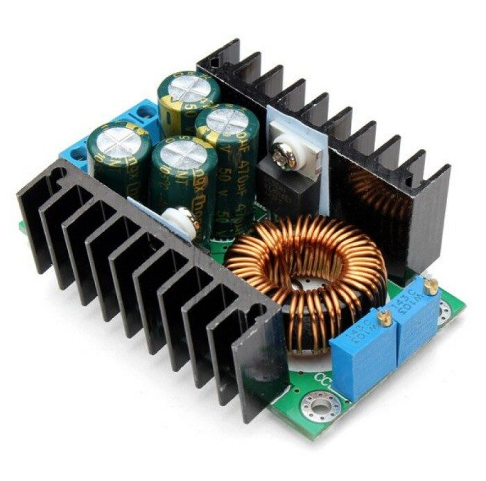
300W 10A DC-DC Step-down Buck Converter Adjustable
High-current buck converter module with built-in input UVLO protection. Ideal for battery-powered high-load projects requiring regulated output.
Practical UVLO Design for LiPo Batteries
Here’s a complete, buildable UVLO circuit for a single-cell 3.7V LiPo battery using an LM393 comparator and TL431 reference:
Components Needed
- LM393 dual comparator IC
- TL431 shunt voltage reference
- R1: 15kΩ 1% metal film resistor
- R2: 10kΩ 1% metal film resistor
- R3: 100kΩ (hysteresis feedback resistor)
- R_pull: 10kΩ (pull-up on comparator output)
- P-channel MOSFET: AO3407 or similar (VGS(th) < -2V)
- Decoupling capacitors: 100nF ceramic
Circuit Operation
The TL431 provides a stable 2.5V reference (connected in programmable mode) to the negative input of the LM393 comparator. The positive input receives the divided battery voltage. When the battery is charged (above 3.2V), the divided voltage exceeds 2.5V → comparator output is open (high via pull-up) → MOSFET gate is pulled to VCC → MOSFET OFF is not what we want, so we invert: use the output to drive a BJT (BC547) whose collector drives the MOSFET gate low.
For simplicity in prototyping, many makers use the BQ29700 — a dedicated single-cell LiPo UVLO IC that handles all this internally, with factory-trimmed 3.0V cutoff and automatic recovery at 3.2V.
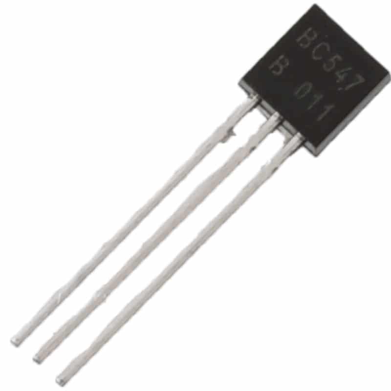
BC547 NPN 100mA Transistor TO-92 (Pack of 10)
Used as gate driver in discrete UVLO circuits. Pack of 10 BC547 transistors — an essential component for any hobbyist electronics toolkit.
Adding Hysteresis to Prevent Oscillation
Without hysteresis, a UVLO circuit near its threshold will rapidly switch on and off — called chattering or hunting. This causes voltage spikes, RF interference, and can damage both the battery and load.
Hysteresis is added by feeding a fraction of the comparator’s output back to its positive input through a large resistor (RHYS). This creates two distinct threshold levels:
- Turn-off threshold (lower): Battery voltage at which output switches LOW
- Turn-on threshold (higher): Battery voltage must rise above this before output switches HIGH again
A good rule of thumb for LiPo applications: set the hysteresis band to 100–200mV. For a turn-off at 3.2V, set turn-on at 3.35–3.4V.
Formula for hysteresis voltage:
VHYS = (VOUT_HIGH × R2) / (RHYS + R2)
Where VOUT_HIGH is the comparator output HIGH voltage (typically equal to VCC through pull-up).

0.1/100nF Multilayer Ceramic Capacitor (Pack of 50)
Decoupling capacitors for UVLO comparator ICs. Essential for preventing noise-induced false trips near the threshold voltage. Pack of 50.
Frequently Asked Questions
What is the difference between UVLO and BMS?
A Battery Management System (BMS) is a comprehensive circuit that handles over-voltage, over-current, over-temperature, and under-voltage protection. UVLO is specifically the under-voltage lockout function — one component of a full BMS. For simple single-cell projects, a standalone UVLO may be sufficient without a full BMS IC.
Can I use UVLO with Arduino projects?
Yes. Connect the UVLO output to the Arduino’s ENABLE pin or use it to cut power to the Vin rail. For a 9V battery powering Arduino, set UVLO at 7.5V to prevent brownout. The ATmega328P’s internal BOD (Brown-Out Detection) fuse can also supplement hardware UVLO.
What UVLO threshold should I use for a 3S LiPo pack?
A 3S LiPo (nominally 11.1V, max 12.6V) should be cut off at 9.6V (3.2V × 3 cells). Set UVLO turn-on recovery at approximately 10.2V. Never discharge a 3S pack below 9.0V (3.0V/cell absolute minimum).
Does UVLO consume battery power when idle?
Yes, but typically very little. A discrete LM393-based circuit draws 1–3mA from the bias resistors. Dedicated nanopower UVLO supervisors (like TPS3840) draw as little as 340nA — negligible even for coin-cell applications.
How do I test my UVLO circuit without draining a real battery?
Use an adjustable bench power supply or a 300W DC-DC buck converter to simulate the battery voltage. Slowly reduce the output voltage while monitoring when the UVLO trips. This lets you verify both the turn-off and recovery thresholds precisely without risking battery damage.
Ready to build your UVLO circuit? Zbotic stocks all the passive components, transistors, and power modules you need. From precision metal film resistors for accurate threshold setting to buck converters with built-in protection — explore our Electronics Components collection and get everything delivered fast across India.


Add comment