
If you’ve ever wondered how autonomous robots “see” and navigate their environment, ultrasonic grid mapping is one of the most accessible entry points. In this tutorial, you’ll learn how to build an ultrasonic grid mapping 2D Arduino robot that sweeps its surroundings with an HC-SR04 sensor, records distances, and reconstructs a simple 2D occupancy grid — all on affordable hardware available in India.
What Is Ultrasonic Grid Mapping?
Grid mapping — also called occupancy grid mapping — divides the robot’s environment into a discrete matrix of cells. Each cell is marked as free, occupied, or unknown based on sensor readings. Traditional research robots use LiDAR costing tens of thousands of rupees, but an HC-SR04 ultrasonic sensor (under ₹50) can generate a surprisingly useful low-resolution 2D map for indoor spaces.
The basic principle: the robot sits at a known starting point, sweeps a servo-mounted ultrasonic sensor across a wide angle, and records the distance to the nearest obstacle at each angle step. Trigonometry converts polar coordinates (angle + distance) into Cartesian (X, Y) grid coordinates. Repeated across many positions as the robot moves, these readings fill in the occupancy grid.
This technique is the foundation of SLAM (Simultaneous Localization and Mapping), the algorithm powering everything from Roomba vacuum cleaners to Mars rovers. Learning it on a small Arduino robot gives you deep intuition for how professional autonomous systems work.
How the System Works
The workflow splits into three phases:
- Sensing: A servo rotates the HC-SR04 from 0° to 180° in 5° steps. At each step, the sensor fires an 8-pulse 40 kHz burst and measures the echo return time. Distance = (time × 343 m/s) / 2.
- Mapping: The Arduino converts each (angle, distance) pair into grid coordinates relative to the robot’s current position and sends the data over serial to a PC (or stores it locally in SRAM if the map is small enough).
- Navigation: A simple wall-following or flood-fill algorithm moves the robot to unexplored cells, then the scan repeats. The cumulative result is a 2D map of the room.
For a beginner build, you can skip autonomous navigation entirely and drive the robot manually with a serial command while the PC collects and renders the map in real time using Python + Matplotlib.
Components You Need
Here is a minimal bill of materials for this project:
- Arduino Uno or Nano (×1)
- HC-SR04 Ultrasonic Sensor (×1)
- SG90 / MG90 Servo Motor (×1) — for sensor pan
- 2WD or 4WD robot chassis with DC motors
- L298N or L293D motor driver module
- 18650 Li-ion battery pack (7.4 V) or 4×AA holder
- Jumper wires, breadboard
- USB cable for serial communication
Optional upgrades: a second HC-SR04 pointing rear or sideways improves map accuracy. Adding an MPU-6050 IMU lets the robot track its heading without wheel encoders.

2WD Mini Round Double-Deck Smart Robot Car Chassis DIY Kit
Compact two-layer acrylic chassis with 2 DC motors, wheels, and hardware — a perfect base for your grid mapping robot.

TowerPro SG90 180 Degree Rotation Servo Motor
Lightweight 9g servo ideal for mounting your ultrasonic sensor for 180° sweep scanning.
Robot Chassis and Motor Setup
A 2WD chassis is easiest for beginners because dead-reckoning odometry (estimating position from wheel turns) only needs to track two wheels. Assemble the chassis per its instructions, then wire the DC motors through an L298N module:
- IN1/IN2 → Arduino D2/D3 (left motor direction)
- IN3/IN4 → Arduino D4/D5 (right motor direction)
- ENA/ENB → Arduino D9/D10 (PWM speed)
- Motor power → 7–12 V battery; Arduino 5 V logic from motor driver’s 5 V output pin
For better odometry, attach optical wheel encoders to each motor shaft. Even cheap IR encoder discs (available from Zbotic) reduce drift from ~30% to under 10% over a 2-metre run. This matters hugely for map accuracy: a 5 cm position error at the far end of a room will merge walls and corridors into a blur.
Mount the servo on the front bumper using a small bracket so the HC-SR04 sits at least 10 cm above the floor. This clears most ground clutter and keeps the sensor above the wheel arches.
Ultrasonic Sensor Sweep Mechanism
The servo sweeps from 0° (right) to 180° (left) relative to the robot’s forward direction. A smaller step size gives denser data but takes more time. At 5° steps you get 37 readings per sweep; at 2° steps you get 91. For a 3 m range, the spatial resolution at max range is roughly distance × sin(step_angle) — about 26 cm at 5° steps. That is sufficient to detect doorways and furniture.
Key gotcha: the HC-SR04 has a dead zone under 2 cm and a maximum reliable range of about 400 cm. Readings outside these bounds should be discarded (set to 0 / max_range sentinel). Also wait at least 60 ms between pings to avoid echo crosstalk from the previous pulse.
For a static sweep, stop the robot, complete a full 0°→180° scan, then move the robot forward a fixed distance and repeat. Stopping eliminates motion blur in the map. Moving continuously is possible but requires timestamps and velocity integration — beyond the scope of a first build.
Arduino Code Walkthrough
Below is a stripped-down version of the core sketch. Full annotated code is available on the Zbotic GitHub examples page.
#include <Servo.h>

const int TRIG = 7, ECHO = 8;
const int SERVO_PIN = 6;
Servo scanServo;

long measureCm() {
  digitalWrite(TRIG, LOW); delayMicroseconds(2);
  digitalWrite(TRIG, HIGH); delayMicroseconds(10);
  digitalWrite(TRIG, LOW);
  long dur = pulseIn(ECHO, HIGH, 25000); // 25ms timeout
  return dur == 0 ? 400 : dur / 58;
}

void setup() {
  Serial.begin(115200);
  pinMode(TRIG, OUTPUT);
  pinMode(ECHO, INPUT);
  scanServo.attach(SERVO_PIN);
}

void loop() {
  for (int angle = 0; angle <= 180; angle += 5) {
    scanServo.write(angle);
    delay(80); // settle time
    long dist = measureCm();
    // Format: angle,distancen
    Serial.print(angle); Serial.print(',');
    Serial.println(dist);
  }
  Serial.println("SCAN_DONE");
  delay(3000); // pause before next sweep
}
On the PC side, a ~30-line Python script reads the serial port, converts polar to Cartesian coordinates, and plots a live scatter map with Matplotlib. Each new scan overlays on the previous one, gradually filling in the environment. When you move the robot, increment a pose counter and apply a translational offset before converting coordinates.
For a more polished build, send robot odometry (wheel encoder ticks) alongside scan data so the Python side can reconstruct the robot’s trajectory and register each scan to the correct world position automatically.
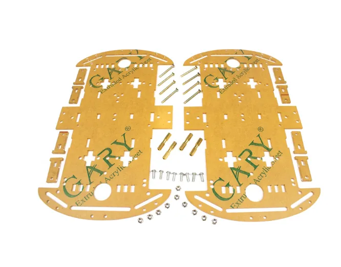
4 Wheels Car Chassis Acrylic Frame
Sturdy 4WD acrylic chassis offering better traction and more stable odometry for mapping robots.
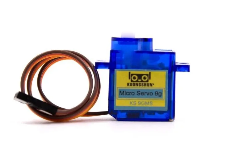
Servo SG90 9g 180 Degree
Affordable 9g servo motor for sensor pan/tilt mechanisms, compatible with all Arduino boards.
Visualising the 2D Map on PC
Install Python 3 with pip install pyserial matplotlib numpy. The mapping script structure:
- Open serial port at 115200 baud.
- Read lines; when you receive
SCAN_DONE, trigger a plot redraw. - Convert each (angle_deg, dist_cm) to (x, y):
x = dist * cos(radians(angle)),y = dist * sin(radians(angle)). - Offset by robot’s current estimated position.
- Scatter-plot all points; use colour intensity to represent confidence (more scans = darker).
Even a simple version of this produces recognisable room outlines within a few scans. You can export the final map as a PNG or save the point cloud as a CSV for later processing in ROS (Robot Operating System) if you want to scale up the project.
Common issues:
- Wavy walls: Robot moved during scan. Always stop before scanning.
- Duplicate walls: Loop closure missed. Add an IMU to track heading changes.
- Short-range artefacts: HC-SR04 dead zone. Filter readings < 3 cm.
- Missing open doorways: Doorframe too narrow for 5° angular resolution. Reduce step to 2°.
Frequently Asked Questions
- Can I use an ESP32 instead of Arduino?
- Yes. The ESP32 adds Wi-Fi so you can stream scan data to a browser-based map renderer instead of using a USB serial cable. The same code works with minor pin changes.
- How accurate is ultrasonic mapping compared to LiDAR?
- HC-SR04 has a ±3 mm distance accuracy but a wide 15° beam angle, causing blooming artefacts near room corners. LiDAR has a narrow beam (0.1°) and much better angular resolution. For hobby use in a 5×5 m room, ultrasonic is perfectly adequate.
- What is the maximum room size this setup can map?
- Practically, about 4×4 m before odometry drift makes the map unreliable. Adding an IMU extends this to ~8×8 m.
- Do I need ROS for this project?
- No. ROS (Robot Operating System) is powerful but heavy. This tutorial uses only Python + Matplotlib and is fully self-contained on any laptop.
- Can I run the mapping algorithm on the Arduino itself?
- Only for very small grids (e.g. 20×20 cells). An Arduino Uno has only 2 KB of SRAM. Use an Arduino Mega for on-board mapping or stream data to a PC/Raspberry Pi.


Add comment