
Every electronics circuit connected to the outside world — whether through USB, GPIO header, power input, or communication lines — is one static discharge or power line transient away from catastrophic failure. TVS diode protection is the industry-standard solution to this problem, and understanding how to select and apply transient voltage suppressors correctly is an essential skill for any electronics engineer or hobbyist. In this guide, we cover everything from ESD fundamentals to TVS clamping behaviour, selection criteria, and real-world PCB placement best practices.
What Is a TVS Diode and How Does It Work?
A Transient Voltage Suppressor (TVS) diode is a solid-state device specifically engineered to protect sensitive electronics from voltage spikes caused by electrostatic discharge (ESD), lightning coupling, inductive switching, and power line disturbances. Unlike a standard Zener diode (which is designed for steady-state regulation), a TVS diode is optimised for extremely fast response (sub-picosecond to a few picoseconds) and can absorb very large instantaneous power pulses — typically ranging from 400W to 30,000W — for very short durations (microseconds to milliseconds).
When the voltage across a TVS diode exceeds its breakdown voltage (also called the standoff voltage), the device switches from a high-impedance state to a low-impedance state within picoseconds, clamping the line voltage to a defined safe level and diverting the transient current away from the protected circuit. When the transient passes, the TVS returns to its high-impedance state automatically.
Think of it as an automatic pressure relief valve for voltage spikes — always watching, instantly responding, and transparently returning to normal once the event passes.
Understanding ESD and Electrical Transients
ESD (Electrostatic Discharge) is the sudden flow of electricity between two objects at different electrical potentials. The classic example is the static shock you get touching a metal doorknob after walking across carpet. In electronics, ESD events happen when a person handles a PCB, when connectors are plugged/unplugged, or during manufacturing. A human body model (HBM) ESD event can deliver a pulse of ±2kV to ±4kV to an unprotected IC pin.
IEC 61000-4-2 ESD Standard
The standard test model for equipment-level ESD protection is IEC 61000-4-2, which defines a contact discharge of ±4kV to ±8kV and an air discharge of ±8kV to ±15kV. Consumer electronics sold in India must comply with this standard. On the other hand, IC-level ESD protection is tested to JEDEC JESD22-A114 (HBM), which uses a 100pF capacitor and 1.5kΩ resistor to simulate the human body — typically testing to ±1kV or ±2kV.
Electrical Fast Transients (EFT) and Surges
Beyond ESD, industrial environments expose equipment to:
- Electrical Fast Transients (EFT): Bursts of rapid spikes from inductive load switching on shared power lines, defined by IEC 61000-4-4 (±1kV to ±4kV, 5/50ns rise/fall)
- Surge transients: Slower, higher-energy events from lightning coupling or capacitor bank switching, defined by IEC 61000-4-5 (±0.5kV to ±4kV, 1.2/50µs wave)
TVS diodes are the first line of defence for ESD and EFT. For surge protection, MOV (Metal Oxide Varistors) are typically used as primary protection, with TVS diodes as secondary protection.
Unidirectional vs Bidirectional TVS Diodes
This is one of the most common points of confusion for beginners, and getting it wrong will either leave your circuit unprotected or cause it to malfunction.
Unidirectional TVS (Asymmetric)
A unidirectional TVS diode behaves like a regular rectifier diode in the forward direction (low forward voltage drop, typically 0.7–1.0V) and like a precision Zener in the reverse direction (clamping at the breakdown voltage). These are used exclusively on DC signal and power lines where the polarity is fixed. They offer better clamping performance (lower overshoot) than bidirectional types for DC lines because of the low forward drop.
Use when: DC power supply rails (5V, 12V, 24V), DC signal lines (GPIO, sensor outputs), one-directional data lines with defined polarity.
Bidirectional TVS (Symmetric)
A bidirectional TVS consists of two Zener diodes connected back-to-back. It clamps voltage transients of either polarity to the same level. It is essential for AC power lines, RS-485/RS-232 communication lines, and any signal that can swing both positive and negative.
Use when: AC signal lines, differential communication buses (RS-485, CAN, USB D+/D-), I/O lines that can be driven negative by inductive kickback, UART lines in noisy industrial environments.
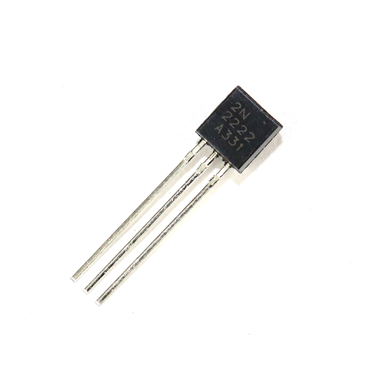
2N2222 NPN Transistor (Pack of 20)
The 2N2222 is commonly used in signal switching circuits where ESD protection on its base input prevents latch-up and junction breakdown from ESD events.
Key TVS Diode Parameters Explained
The TVS datasheet can look intimidating at first, but there are only a handful of parameters you need to understand for practical circuit design:
Standoff Voltage (V_WM or V_RWM)
This is the maximum continuous working voltage — the highest voltage the TVS can see without conducting. You must select a TVS with a standoff voltage equal to or higher than the maximum normal operating voltage on the protected line. For a 5V line, use a TVS with V_WM ≥ 5V (e.g., a 5V or 5.5V standoff TVS). Never use a TVS with V_WM lower than your operating voltage, or it will conduct continuously and overheat.
Breakdown Voltage (V_BR)
The voltage at which the TVS starts to conduct (measured at a specified test current, typically 1mA). Due to manufacturing tolerances, V_BR is specified as a min/max range, typically ±5% or ±10% of the nominal value. For a 5V line, a SMBJ5.0 TVS has V_BR(min) = 6.4V and V_BR(max) = 7.07V.
Clamping Voltage (V_C)
This is the most important parameter from a protection perspective. V_C is the peak voltage across the TVS when it is conducting its rated peak pulse current (I_PP). This is the voltage your protected circuit will actually see during a transient event. You must ensure V_C is below the absolute maximum voltage rating of your protected IC or component. For a 5V MCU with maximum tolerable input of 6V, you need a TVS with V_C ≤ 6V at your expected peak transient current.
Peak Pulse Power (P_PP)
The maximum instantaneous power the TVS can absorb without damage, for a specified pulse waveform (usually 8/20µs for EFT or 10/1000µs for surge). Common ratings for through-hole TVS diodes are 400W (P4SMA series), 600W (P6SMB series), 1500W (1.5KE series), and 3000W (3KP series). For general ESD protection on PCBs, 400–600W is usually adequate.
Junction Capacitance (C_J)
TVS diodes have significant junction capacitance, which can be a problem on high-speed data lines. A standard 400W through-hole TVS may have 100–1000pF of capacitance, which will filter or distort high-speed signals. For USB 2.0 (480Mbps), you need a TVS with capacitance below 10pF. For USB 3.0 (5Gbps), it needs to be below 0.5pF. Low-capacitance TVS arrays (like the PRTR5V0U2X or USBLC6-2SC6) are available in SMD packages for high-speed line protection.
How to Select the Right TVS Diode
Here is a step-by-step selection process you can follow for any protection design:
- Determine the operating voltage of the protected line (e.g., 5V, 12V, 24V)
- Select standoff voltage V_WM ≥ maximum operating voltage with a small margin (5–10%). For a 12V line, choose V_WM = 12V or 13V.
- Choose polarity: unidirectional for DC, bidirectional for AC or differential lines
- Verify clamping voltage V_C is below the absolute maximum input voltage of the protected device at the expected peak transient current
- Calculate required peak pulse power: P_PP = V_C × I_PP, where I_PP = (V_surge_peak – V_C) / R_source. For most PCB-level ESD protection, 400–1500W TVS are adequate.
- Check junction capacitance if used on signals above 1Mbps. Low-cap TVS arrays may be needed.
- Select package: SMA/SMB/SMC for surface mount, DO-214AB/DO-15 for through-hole, SOT-23 arrays for multi-channel low-current protection.
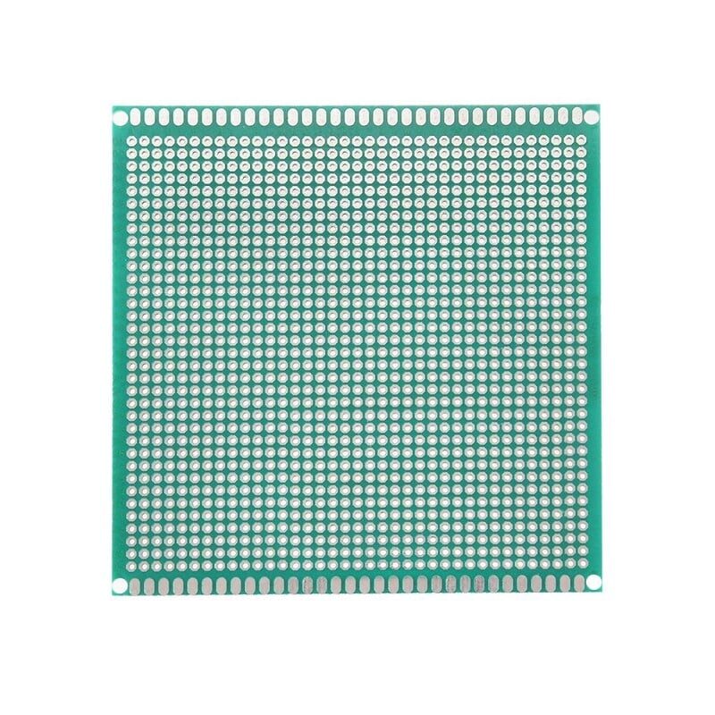
10×10 cm Universal PCB Prototype Board
Build and test your TVS diode protection circuits on this reliable single-sided perfboard before moving to custom PCB production.
PCB Layout and Placement Best Practices
A TVS diode that is perfectly selected but poorly placed on the PCB provides far less protection than you think. The golden rules of TVS placement are:
Place TVS at the Entry Point
The TVS must be placed at the entry point of the signal or power line — right at the connector or where the line enters the PCB. If you place the TVS 5cm away from the connector with a long PCB trace in between, the trace inductance will allow the spike to pass and damage your circuit before the TVS can clamp it. The rule of thumb is: place the TVS within 5mm of the connector.
Keep the Protection Loop Short
The current path for a clamped transient is: External source → TVS anode → TVS → TVS cathode → Ground. Any inductance in this loop (trace length, vias) increases the effective clamping voltage seen by the protected circuit. Keep this loop area to an absolute minimum. Use wide traces from the TVS cathode directly to the nearest ground pour with a short via.
Separate Protection Ground from Signal Ground
If your TVS is discharging a large ESD pulse, that current flows through the ground trace. If this shares the same ground trace as your sensitive signal circuitry, the pulse will inject noise into your measurements. Use a dedicated wide ground trace or ground pour from the TVS to the chassis/earth ground, and connect it to circuit ground only at one point (star ground topology).
Place Series Resistor Before TVS on High-Speed Lines
For RS-232, I2C, and similar lines, a small series resistor (22–100Ω) placed before the TVS acts as a current limiter and, combined with the TVS junction capacitance, forms a simple low-pass RC filter. This reduces the ESD current magnitude the TVS must handle and also provides additional filtering of the transient. This is the classic “series R + shunt TVS” topology seen in reference designs from STMicroelectronics and Texas Instruments.
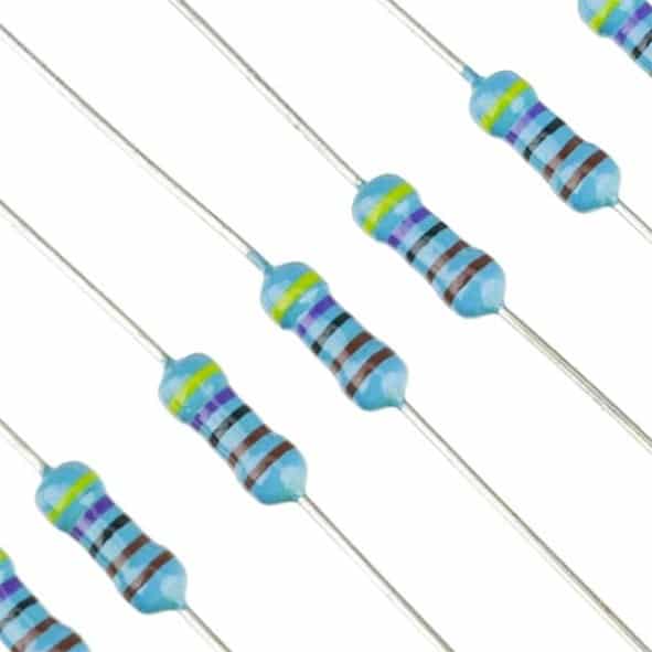
Metal Film Resistors MFR 1/4W (Pack of 100)
Low-noise metal film resistors for series protection networks. Metal film types offer better noise performance than carbon film for sensitive signal protection circuits.
Common Applications for Indian Makers
Arduino/Raspberry Pi GPIO Protection
GPIO pins on microcontrollers are extremely vulnerable to ESD. A single static discharge from a human finger during prototyping can permanently latch up an input pin. Place a bidirectional TVS (e.g., PRTR5V0U2X or individual 5V bidirectional TVS) on each externally accessible GPIO. For multiple GPIOs, multi-channel TVS arrays in SOT-363 or DFN packages save space.
Relay and Inductive Load Driver Protection
When a relay coil is switched off, the voltage spike at the driver transistor’s collector (or MOSFET’s drain) can exceed 100V even on a 12V system. A unidirectional TVS rated for your supply voltage (e.g., a 15V unidirectional TVS on a 12V relay driver) provides a hard clamp. This is faster than a 1N4007 freewheeling diode and provides a defined voltage limit, making it preferred for high-frequency switching where the freewheeling diode may not recover fast enough.
Sensor Interface Protection
Temperature sensors like LM35 and humidity sensors like DHT11 are often deployed outdoors or in industrial environments where long cable runs pick up transient noise. A TVS on the signal and supply lines at the PCB entry point prevents false readings and sensor destruction from cable-induced transients.

LM35 Temperature Sensor
The LM35 is a popular analog temperature sensor — add a TVS diode and series resistor on its output line when deploying in industrial or outdoor environments for reliable, damage-free operation.
Frequently Asked Questions
What is the difference between a TVS diode and a MOV (Metal Oxide Varistor)?
TVS diodes are silicon semiconductor devices with very precise, tight voltage clamping tolerances, fast response times (picoseconds), and longer operational life. MOVs are ceramic varistors with slower response (tens of nanoseconds), larger energy handling capability, and wider voltage tolerances. For ESD and fast transient protection on PCB signal lines, TVS diodes are the right choice. For AC mains line surge protection (lightning, power surges), MOVs are typically used as primary protection, sometimes combined with a TVS as secondary protection.
Can I use a Zener diode instead of a TVS diode for ESD protection?
Technically yes, but a Zener diode is not a good substitute. Zener diodes are designed for continuous voltage regulation and have very limited peak pulse power handling capability (typically under 1W). A TVS diode of the same package size can handle 400–1500W peak pulse power because it is optimised for large-area junction design specifically for pulse absorption. Using a Zener for ESD protection is like trying to stop a flood with a garden hose.
My TVS diode is getting hot in normal operation. What is wrong?
If a TVS is getting hot continuously, it is conducting continuously — meaning the operating voltage on that line exceeds the TVS’s standoff voltage. Check the actual voltage on the line with a multimeter and compare it to the TVS’s V_WM rating. You either have the wrong TVS (too low a standoff voltage) or your power supply is running higher than expected. Replace with a TVS that has a higher standoff voltage.
How many TVS diodes do I need for full ESD protection on a multi-pin connector?
Each line that enters the PCB from an external connector and connects to a sensitive IC pin needs its own TVS protection. However, you do not need individual discrete TVS diodes — multi-channel TVS arrays protect 2 to 8 channels in a single small package (e.g., PRTR5V0U2X for 2 USB lines, ESD8D5V0L1B for 8 lines). This is the standard approach in commercial designs.
Does a TVS diode provide reverse polarity protection?
A unidirectional TVS diode provides a low-impedance path in the forward direction, which effectively protects against reverse polarity on DC lines by shorting the reversed supply through its forward bias. However, this will blow the supply fuse or damage the supply if the TVS is not rated for the current. For dedicated reverse polarity protection, use a Schottky diode in series with the supply, or a P-channel MOSFET circuit.
Protect Your Circuits Before It Is Too Late
ESD and transient events are silent killers — your circuit works fine until one day it simply doesn’t. Explore Zbotic’s range of passive components and use them to build robust protection networks for all your Arduino, Raspberry Pi, and custom PCB projects.


Add comment