
If you have ever noticed the difference between the electricity consumed shown on your meter and what your appliances seem to use, or wondered why Indian electricity boards charge commercial establishments extra for low power factor, then you have encountered one of the most important but least understood concepts in AC electrical engineering. Power factor explained simply: it is the measure of how efficiently your electrical load converts incoming power into useful work. In this comprehensive guide, we will break down power factor, reactive power, correction techniques, and why it matters for both Indian households and electronics makers.
Table of Contents
- What Is Power Factor?
- Real Power, Reactive Power, and Apparent Power
- Why Low Power Factor Is a Problem in India
- What Causes Low Power Factor?
- Power Factor Correction: Capacitor Banks and More
- Power Factor in Electronics: SMPS and LED Drivers
- Measuring Power Factor at Home
- Recommended Products
- Frequently Asked Questions
What Is Power Factor?
Power Factor (PF) is a dimensionless number between 0 and 1 (or equivalently, 0% to 100%) that describes the ratio of real (useful) power consumed by a load to the apparent (total) power drawn from the supply. Mathematically:
Power Factor = Real Power (W) / Apparent Power (VA)
A power factor of 1.0 (unity) means 100% of the power drawn from the supply is converted to useful work. A power factor of 0.7 means only 70% is doing useful work — the remaining 30% is circulating back and forth between the source and load without doing any work, but still flowing through the wires and causing losses.
For purely resistive loads (incandescent bulbs, electric heaters, nichrome heating elements), the current is perfectly in phase with the voltage. The power factor is 1.0. All the power is consumed as heat or light — useful work.
For loads with inductance (motors, transformers, fluorescent tube ballasts) or capacitance, the current is phase-shifted relative to the voltage. The current and voltage waveforms are not in sync. This phase difference is the root cause of power factor less than 1.
The phase angle between voltage and current is denoted by θ (theta), and:
Power Factor = cos(θ)
This is why power factor is also called cos φ in many Indian electrical engineering texts and meter specifications.
Real Power, Reactive Power, and Apparent Power
To fully understand power factor, you need to understand the power triangle — the three types of power in AC circuits:
Real Power (P) — Watts (W)
Real power is the power that actually does useful work — running a motor, producing light, generating heat. It is what your electricity meter (kWh meter) measures. Real power is consumed irreversibly by the resistive component of a load.
Reactive Power (Q) — Volt-Ampere Reactive (VAR)
Reactive power is the power that oscillates between the source and the reactive components (inductors and capacitors) of the load. It does no net work over a complete cycle — it simply charges and discharges the magnetic field of an inductor or the electric field of a capacitor. However, it does flow through the wires, creating I²R heating losses in conductors, transformer windings, and distribution equipment.
Inductive loads (motors, chokes) consume reactive power (lagging power factor). Capacitive loads produce reactive power (leading power factor). This is why capacitors are used to correct lagging power factor — they supply the reactive power locally so it does not have to travel from the generating station.
Apparent Power (S) — Volt-Ampere (VA)
Apparent power is the product of the RMS voltage and RMS current: S = V × I. It is what the utility must supply — it includes both real and reactive components. Generators, transformers, and cables must be rated for apparent power (in VA or kVA), not just real power (kW). This is why a UPS is rated in VA: a 1kVA UPS does not necessarily deliver 1kW of real power — it depends on the power factor of the connected load.
The Power Triangle
The three quantities form a right triangle:
- Hypotenuse = Apparent Power (S) in VA
- Horizontal side = Real Power (P) in W
- Vertical side = Reactive Power (Q) in VAR
- S² = P² + Q²
- Power Factor = P / S = cos(θ)
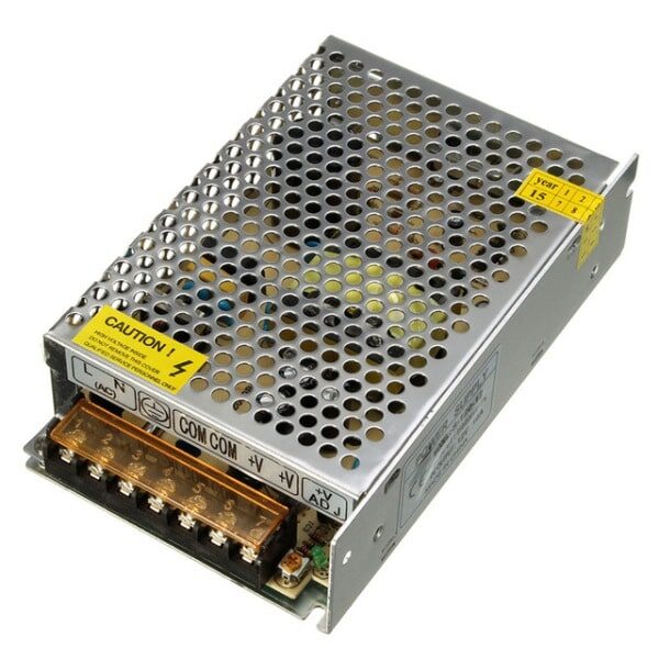
12V 10A SMPS – 120W – DC Metal Power Supply
Modern SMPS units include active power factor correction (APFC) circuits that maintain a power factor of 0.95 or better — much more efficient than old linear transformer supplies. This 120W unit is ideal for powering maker projects from India’s 230V supply.
Why Low Power Factor Is a Problem in India
Low power factor has significant economic and technical consequences — especially in a country like India where electricity infrastructure is already under strain in many regions.
For Electricity Distribution (The Utility’s Problem)
- Increased current for same real power: At PF = 0.7, delivering 700W of real power requires 1000VA of apparent power — meaning 1000/230 ≈ 4.35A of current must flow through the wires. At unity PF, only 700/230 ≈ 3.04A is needed. The extra current heats the wires and transformers without delivering useful energy.
- Transformer and cable overloading: Distribution transformers and cables are rated in VA, not W. Low PF wastes their capacity on reactive current that could have served more customers.
- Voltage regulation problems: High reactive current creates larger voltage drops across distribution lines, causing supply voltage to fall below the regulated level — exactly what causes the low-voltage problems common in many Indian towns and rural areas.
For Commercial and Industrial Consumers in India
The Central Electricity Regulatory Commission (CERC) and state DISCOMs in India have tariff provisions that penalise consumers (typically large commercial and industrial consumers) for low power factor — typically below 0.85 or 0.90. Some DISCOMs also offer incentives (rebates on the energy bill) for consumers who maintain a power factor above 0.95 or 0.98. For large factories with motors and inductive loads, investing in power factor correction capacitor banks can pay for itself within months through electricity bill savings.
For Households
Residential consumers in India are generally not directly billed for reactive power — their kWh meters measure only real power (watts). However, they still indirectly pay through higher electricity tariffs that the utility uses to recover its costs from distribution losses caused by poor power factor across the grid. LED lighting and modern inverter ACs have helped improve household power factor significantly in recent years.
What Causes Low Power Factor?
The primary causes of low (lagging) power factor in Indian homes and industries:
- Induction motors: The most significant contributor. Induction motors (pumps, compressors, fans, industrial machinery) draw a large magnetising reactive current to establish their rotating magnetic field. A lightly loaded motor has an even worse power factor than a fully loaded one.
- Fluorescent lights with electromagnetic ballasts: Traditional choke-ballast tube lights have a power factor of 0.5-0.6. A building full of old fluorescent tube lights is a major reactive power consumer. Modern electronic ballasts and LED drivers have much better PF (0.9-0.99 with PFC).
- Transformer losses: Transformers draw a magnetising current even at no load — this is reactive power.
- Old-style power supplies: Simple capacitor-input rectifier circuits (common in cheap adapters) draw current in large pulses rather than sinusoidally, creating harmonic distortion and a poor power factor (as low as 0.5-0.65).
- UPS systems: Older ferroresonant and some online UPS units have poor input power factor. Modern UPS systems with APFC are far better.
Power Factor Correction: Capacitor Banks and More
Since most loads in India have lagging power factor (inductive), the most common correction method is adding capacitance to the circuit. Capacitors have leading reactive power that directly cancels the lagging reactive power of inductive loads.
Fixed Capacitor Banks
The simplest approach is a fixed capacitor connected directly across the supply at the point of use (e.g., across an induction motor’s supply terminals). The capacitor value is chosen to compensate for the expected reactive power demand. This is used in ceiling fans (the capacitor in the fan box), single-phase induction motors, and old fluorescent tube light fittings.
Automatic Power Factor Control (APFC) Panels
For large industrial loads with varying power factor, fixed capacitors may either under-correct or over-correct (leading to a capacitive power factor). An APFC panel uses a controller that continuously measures the power factor and switches capacitor banks in and out automatically to maintain a target power factor (typically 0.95-0.99 lagging).
Active Power Factor Correction (APFC) in Electronics
Modern switching power supplies include an Active PFC stage — a boost converter circuit that reshapes the input current waveform to closely follow the sinusoidal voltage waveform, achieving a power factor of 0.95-0.99. This is now mandatory in many countries and is standard in quality PC power supplies, LED drivers, and industrial SMPS units. The BIS and ESMA standards in India increasingly require PFC for higher-power electronic equipment.
Why PF Above Unity Is Not Achievable (and Not Needed)
You cannot have a power factor greater than 1.0 — this would violate energy conservation. However, you can have a capacitive (leading) power factor, where the capacitor bank over-corrects for inductive loads. This is actually undesirable and utilities prefer a slightly lagging PF (0.95-0.99 lagging) rather than a leading PF, because leading PF causes voltage to rise above nominal on the distribution lines.
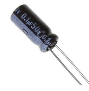
0.1µF 50V Capacitor (Pack of 50)
Study capacitive reactive power correction hands-on. These 50V-rated capacitors can be used in lab experiments to observe power factor correction in small inductive circuits, or as decoupling components in electronics projects.
Power Factor in Electronics: SMPS and LED Drivers
Power factor is not just a utility-scale concern — it is directly relevant to the electronics projects that Indian makers build and use.
SMPS Without PFC
A basic, cheap SMPS (capacitor-input design without active PFC) draws current in sharp pulses at the peaks of the AC voltage waveform. This results in a power factor of 0.5-0.65 and generates harmonic currents that stress the neutral conductor and other equipment on the same circuit. Many cheap phone chargers, LED drivers, and power bricks from China (and some low-cost Indian brands) fall into this category.
SMPS With Active PFC
A quality SMPS includes a boost PFC stage before the main converter. This draws sinusoidal current from the mains, achieving PF > 0.95. These are heavier and slightly more expensive, but generate less heat, stress the mains wiring less, and comply with BIS/CE/UL standards. When buying an SMPS for your maker project, look for one that specifies PFC — it is a sign of quality.
LED Drivers and PF
LED bulbs vary enormously in power factor. Cheap LED bulbs (non-PFC driver) may have PF as low as 0.5 — meaning a 10W LED actually draws 20VA of apparent power from the supply. Quality LED bulbs and commercial LED drivers specify PF > 0.9. For your own LED projects using LED strip lights, choose a 12V SMPS with active PFC for best efficiency.
AC-DC Buck Converters for Makers
AC-to-DC modules (like the 150W AC-DC buck converter) that are popular in maker projects also vary in their power factor. The better quality modules include basic PFC to keep their input current distortion manageable. Always check the input specifications of any AC-to-DC module before deploying it in a product.
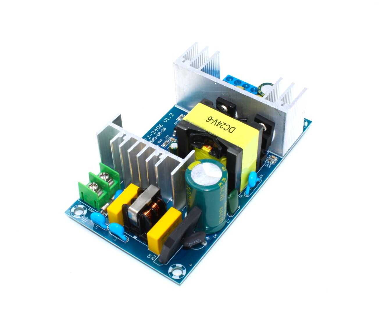
150W AC-DC Buck Converter 100V-240V to 24V 6A-9A
A wide-input (100V-240V) AC-DC module that works directly from India’s 230V mains to produce 24V DC output at up to 9A. Suitable for 24V CNC systems, LED driver projects, and industrial control applications.
Measuring Power Factor at Home
Wondering what the power factor of your home appliances is? Here are practical methods:
Using a Kill-A-Watt / Energy Monitor
Plug-in energy monitors (sold under various brands in India for ₹500-₹2000) display Watts (W), Volt-Amperes (VA), and often power factor directly. Plug in your appliance and read off the PF. You may be surprised — your old refrigerator may show 0.7 PF, your LED TV 0.9 PF, and your modern inverter AC 0.95-0.99 PF.
Using a Clamp Meter with PF Measurement
Many modern clamp meters (₹2000-₹5000 range) include VA and PF measurement. Clip around the live wire of the appliance’s power cord and read the PF display. Professional electricians use this to assess industrial loads before and after installing capacitor banks.
Calculation Method (Lab Setting)
Measure the true RMS voltage (V), true RMS current (I), and true watts (W) using appropriate meters. Then PF = W / (V × I). Note that a standard non-true-RMS multimeter will give incorrect readings for distorted AC waveforms — you need a true-RMS instrument for accurate PF-related measurements.

LCR-T4 LCD Graphical Transistor Tester — Resistance, Capacitance, ESR, SCR Meter
Measure the capacitance and ESR of capacitors used in power factor correction circuits. This multi-function LCR tester also identifies and measures resistors, inductors, transistors, and diodes — an essential tool for any maker’s workbench.
Frequently Asked Questions
Q: Will improving power factor reduce my home electricity bill?
For most Indian residential consumers: probably not directly, since residential kWh meters measure only real power (watts). However, if you are a large commercial consumer billed with a PF penalty clause by your DISCOM, improving PF to above the threshold (typically 0.90-0.95) will eliminate the penalty and may earn you a rebate. Check your electricity bill tariff schedule for the specific clause applicable to your connection.
Q: My UPS is rated 1kVA. Why does it only supply 600W?
The 1kVA is the apparent power (VA) rating. At a typical connected load power factor of 0.6, the real power (W) available is 1000VA × 0.6 = 600W. Modern UPS specifications often list both: e.g., “1000VA / 900W” — the latter assuming a 0.9 PF load (modern electronic loads like computers have high PF). For older UPS models, always check the watt rating, not just the VA rating.
Q: Can a capacitor really fix the power factor of an induction motor?
Yes — this is exactly how ceiling fan capacitors work. The capacitor in your ceiling fan’s speed regulator box is a power factor correction capacitor for the single-phase induction motor. It also serves to create the phase difference needed to start a single-phase motor. Industrial capacitor banks work on the same principle at much larger scale.
Q: What power factor do modern LED lights have?
It varies widely by quality. Budget LED bulbs (₹50-₹100 range) often have PF of 0.5-0.7 with no PFC. Mid-range and branded LED bulbs (Philips, Syska, Wipro) typically achieve PF of 0.85-0.95. Commercial LED drivers for installations specify PF > 0.90 or > 0.95. When buying LED bulbs in bulk for a large installation, always check the PF specification.
Q: Is power factor the same as efficiency?
No, these are different concepts, though both are ratios. Efficiency = (Output Power) / (Input Power) — it measures how much power is lost as heat or waste within the device. Power factor = (Real Power) / (Apparent Power) — it measures how much of the supplied apparent power is doing real work versus circulating as reactive power. A device can be highly efficient (low internal losses) but have poor power factor (drawing large reactive current), or vice versa.
Explore electronics fundamentals with quality components. Find capacitors, power supplies, SMPS units, and test equipment at Zbotic Electronics Components — your trusted source for maker supplies across India, with fast shipping from our warehouse.


Add comment