
The TP4056 is one of the most popular 1A single-cell lithium battery charging ICs in the world, and it is a staple component in almost every Indian electronics hobbyist’s toolkit. However, there is consistent confusion about the TP4056 with protection module versus the bare TP4056 board. Buying the wrong one for your project can either leave your battery vulnerable to damage or add unnecessary bulk to a space-constrained design. This guide settles the debate once and for all.
What Is the TP4056 IC?
The TP4056 is a complete constant-current/constant-voltage (CC/CV) linear charger IC designed specifically for single-cell 4.2V lithium-ion and lithium-polymer batteries. Manufactured by NanJing Top Power ASIC Corp, it comes in an SOP-8 package and requires minimal external components — just a few resistors and capacitors.
Key specifications of the TP4056 IC:
- Charging voltage: 4.2V ± 1.5% (fixed)
- Maximum charging current: 1000mA (set by a single external resistor)
- Input voltage range: 4.5V to 5.5V (USB-compatible)
- Trickle charge for deeply discharged cells
- Automatic recharge when battery drops below 4.05V
- LED indicators for charge status (charging / complete)
The IC itself only handles charging. It does NOT protect the battery from over-discharge, over-charge (beyond what it already controls), or short circuits during load use. This is where the two module variants diverge.
TP4056 Without Protection – How It Works
The bare TP4056 module — also sold as the “TP4056 Type-C charging board” or “Mini USB TP4056” — contains only the TP4056 IC and its supporting components: input capacitors, a programming resistor for current, status LEDs, and the USB connector.
This module charges the connected lithium cell correctly, cutting off at 4.2V and indicating completion via the LED. However, when you connect a load (like an Arduino, motor driver, or LED strip) directly to the battery terminals of this module, there is nothing stopping you from:
- Over-discharging the cell below 2.5V, permanently degrading capacity
- Short-circuiting the battery through a faulty load, potentially causing a fire
- Drawing current while charging, which can cause undesired behaviour in the TP4056’s charge termination logic
The without-protection module is typically a single-sided PCB, smaller in size, and costs a few rupees less. It is suitable when your downstream circuit already has its own protection, or when you are only charging a battery that will be disconnected before use.
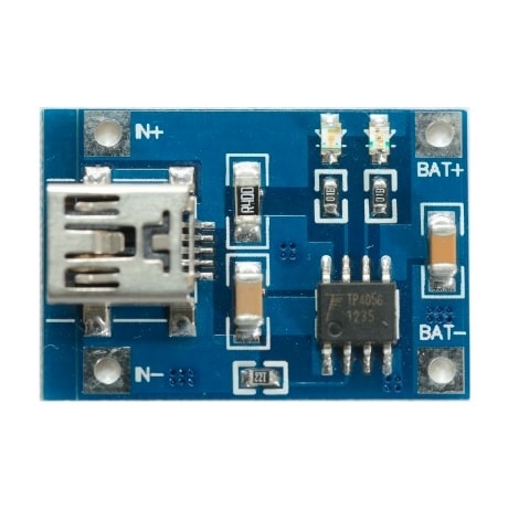
TP4056 1A Li-ion Charging Module – Mini USB (Without Protection)
Classic bare TP4056 charging board with Mini USB input. Ideal when you have a separate BMS or protection circuit downstream, or for dedicated charge-only applications.
TP4056 With Protection – What’s Added?
The TP4056 with protection module adds a second IC — usually the DW01A (or its equivalent FS8205A MOSFET pair) — on the same PCB. This combination creates a complete battery management system in one tiny module. The DW01A is a dedicated lithium battery protection IC that monitors the battery in real time and cuts off the output under fault conditions.
What the protection circuit adds:
- Over-discharge protection: Cuts load output when cell voltage drops below ~2.5V–3.0V (depending on threshold). The cell is saved from permanent damage.
- Over-charge protection: Acts as a secondary failsafe above the TP4056’s 4.2V cutoff (triggers at ~4.28V)
- Over-current / short-circuit protection: Disconnects output instantly if current exceeds safe limits, protecting the battery from heat and fire
Physically, the with-protection module is slightly larger (usually double-sided PCB with components on both sides) and has separate charging terminals (B+ / B–) and output terminals (OUT+ / OUT– or labelled as BAT+ and Load+). This is a critical distinction that confuses many beginners — the battery connects to the BAT pads, and your load connects to the OUT pads. Never bypass this.
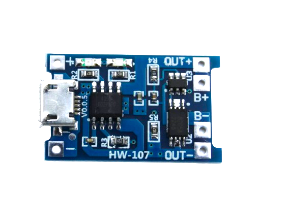
TP4056 1A Li-ion Battery Charging Board – Micro USB with Protection
The most popular TP4056 module for DIY projects. Includes over-discharge, over-current and short-circuit protection via DW01A IC. Use this as the default choice for any standalone battery-powered project.
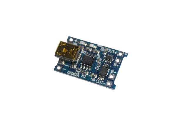
TP4056 1A Li-ion Charging Module – Mini USB with Protection
Same protection as the Micro USB version but with a Mini USB connector. Suitable for projects where Mini USB is the available charging port.
Key Differences: Side-by-Side Comparison
| Feature | Without Protection | With Protection (DW01A) |
|---|---|---|
| Charging voltage cutoff | 4.2V | 4.2V + secondary at 4.28V |
| Over-discharge protection | No | Yes (~2.5–3.0V cutoff) |
| Short-circuit protection | No | Yes (instantaneous cutoff) |
| Separate load output | No | Yes (OUT+ / OUT–) |
| Board size | Smaller | Slightly larger |
| Price difference | Slightly cheaper | ₹2–5 more |
| Simultaneous charge + load | Problematic | Yes (path-through charging) |
Which One Should You Buy?
The answer is almost always the TP4056 with protection module, unless you have a specific reason not to. Here is the decision framework:
Choose the WITH Protection module when:
- You are building a portable device powered by the battery (Arduino, NodeMCU, sensors, LED project, etc.)
- You want the battery to also charge while the device is running (“pass-through” or “path charging”)
- You are a beginner and want maximum safety with minimal design effort
- You are using unprotected 18650 cells (most raw cells have no internal protection)
Choose the WITHOUT Protection module when:
- Your circuit already has a dedicated BMS downstream (common in multi-cell pack builds)
- You are building a dedicated charge-only dock where the load is always disconnected during charging
- You are using protected 18650 cells (cells with a PCB at the negative terminal) and need to save space
- Your project has a separate voltage regulator with under-voltage lockout (UVLO) that handles over-discharge protection
For the ₹2–5 price difference at Zbotic, there is no financial reason to compromise on safety. When in doubt, always buy the protected version.
Wiring Guide for Both Modules
Wiring the WITHOUT Protection Module:
USB 5V Input  →  VIN / USB connector
Battery +     →  BAT+ pad
Battery –     →  BAT– pad
Load +        →  Direct to BAT+ (no protection path)
Load –        →  Direct to BAT–
Wiring the WITH Protection Module:
USB 5V Input  →  VIN / USB connector
Battery +     →  B+ pad (battery connection)
Battery –     →  B– pad (battery connection)
Load +        →  OUT+ pad (protected output)
Load –        →  OUT– pad (protected output)

IMPORTANT: Never connect load to B+/B– directly — use OUT+ / OUT– only!
A common mistake is wiring the load to the BAT pads on the protected module, bypassing the protection entirely. The OUT pads always go through the DW01A protection FETs.
Common Mistakes with TP4056 Modules
- Using a non-current-limited 5V supply: The TP4056 charges at up to 1A. If your USB adapter is a cheap 500mA phone charger, it may trigger overcurrent protection or deliver poor charging. Use a proper 5V 2A adapter.
- Confusing the BAT and OUT pads on the protected module: As described above — load must always connect to OUT, not BAT.
- Running high-current loads through the TP4056: The DW01A protection FETs on the module are typically rated for 3A maximum. Do not power motors or high-draw peripherals directly through the module output.
- Daisy-chaining multiple modules for higher current: This does not work as intended. For higher charging current, use a dedicated charger IC rated for the required current.
- Assuming the protection module replaces a BMS for multi-cell packs: The TP4056 only handles single-cell (3.7V) batteries. For 2S, 3S, or larger packs, you need a dedicated BMS circuit.
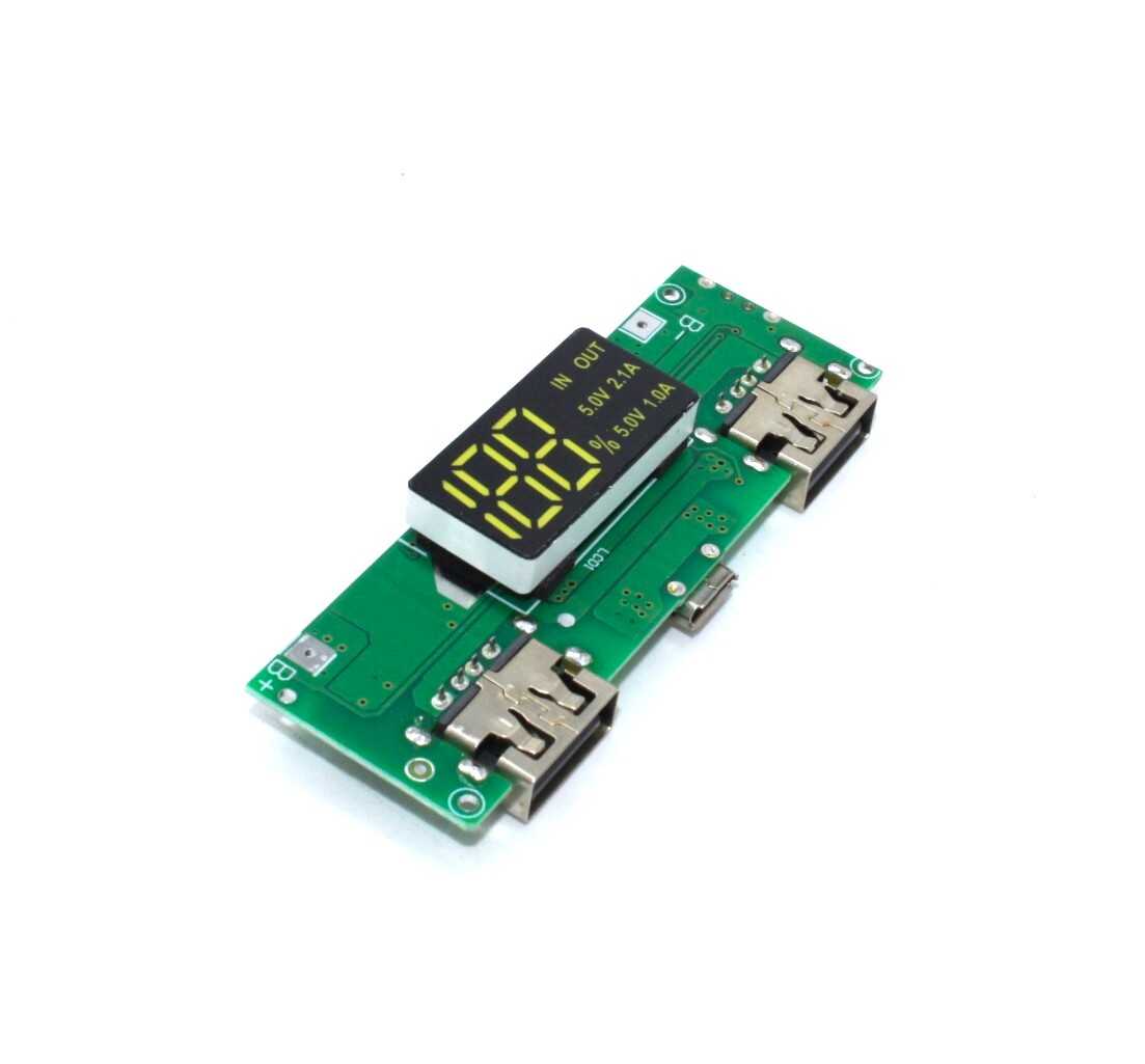
18650 5V 1A/2A Lithium Battery Charging Module – Dual USB + Display
Complete DIY power bank module: charges 18650 via Micro USB, outputs regulated 5V on dual USB ports with a digital display showing battery level. Perfect for portable projects.
Frequently Asked Questions
Can I charge and use the load at the same time with the TP4056 protection module?
Yes. The protected module supports pass-through or path charging. When USB is connected, the TP4056 charges the battery, and the load draws power simultaneously. However, if the load current is greater than the charging current (1A), the battery will also discharge while charging — this is normal and safe with the protected module.
What is the maximum load current the TP4056 protection module can supply?
The output FETs on most DW01A-based modules are rated for approximately 3A continuous. The battery’s own discharge capability is usually the limiting factor. For loads above 2A, consider using a separate BMS IC rated for higher current.
Why does my TP4056 module blink both LEDs?
Both LEDs blinking simultaneously usually indicates the battery voltage is too low (deeply discharged) and the TP4056 has entered trickle charge mode. This is normal. If the condition persists for more than 30 minutes, the battery may be too deeply discharged to recover.
Can I use the TP4056 module to charge protected 18650 cells?
Yes, you can. However, combining a protected 18650 cell with the protected TP4056 module gives you double protection, which is harmless. Just be aware that if the cell’s internal protection PCB trips, the whole system will appear to stop working — remove the cell and recover it with a slow-charge technique.
Is the TP4056 module safe for LiPo pouch cells?
Yes, as long as the LiPo cell is a single-cell 3.7V type. The TP4056 charges to exactly 4.2V, which is the correct maximum for standard LiPo cells. Do not use it for LiHv cells that charge to 4.35V.
Shop TP4056 charging modules, 18650 battery holders, and BMS protection boards at Zbotic — India’s trusted source for maker electronics.

Add comment