
Table of Contents
- Why Vref Matters for Stepper Motors
- A4988 Driver Overview
- Vref Formula Explained
- Step-by-Step Vref Setting Procedure
- Practical Example: NEMA17 Motor
- Heat, Cooling & Duty Cycle
- Microstepping and Current
- Common Mistakes & Fixes
- Recommended Products from Zbotic
- FAQ
Why Vref Matters for Stepper Motors
If your stepper motor is skipping steps, overheating, vibrating excessively, or simply not moving, there is a very good chance the current limit on your driver is set incorrectly. The A4988 is one of the most popular stepper motor driver ICs used in 3D printers, CNC machines, laser cutters, and general robotics projects across India. Its current-limiting feature is controlled through a small onboard potentiometer that sets a reference voltage known as Vref.
Setting Vref too high forces more current through the motor coils than they are rated to handle, causing overheating and potential burnout. Setting it too low starves the motor of torque, resulting in missed steps and erratic movement. Getting this value right is one of the most important calibration tasks for any motion-control project.
This guide walks you through the exact formula, the measurement procedure, common pitfalls, and real-world tips for getting your A4988 Vref dialled in perfectly — even if you are a beginner.
A4988 Driver Overview
The A4988 is a micro-stepping bipolar stepper motor driver from Allegro MicroSystems. Key specifications to remember:
- Supply voltage (VMOT): 8 V to 35 V
- Logic voltage (VDD): 3.3 V or 5 V
- Maximum continuous output current: 1 A per coil (with adequate heat dissipation)
- Peak current: up to 2 A per coil with a heat sink
- Microstepping modes: Full, 1/2, 1/4, 1/8, 1/16 — selectable via MS1, MS2, MS3 pins
- Built-in overcurrent protection and thermal shutdown
The driver uses a technique called PWM current chopping to regulate current through each motor coil. It compares the actual coil current (sensed via small onboard resistors called Rsense or Rs) against the Vref voltage to decide when to switch the coil drive on and off. Therefore, Vref directly determines the maximum current delivered to the motor.
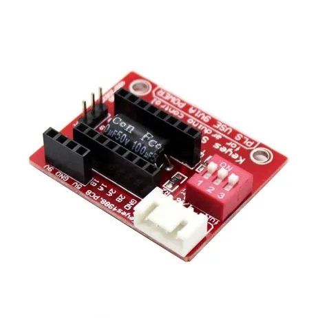
A4988 Stepper Motor Driver Controller Board – RED
The most widely used stepper motor driver for 3D printers and CNC projects. Features adjustable Vref potentiometer, thermal shutdown, and micro-stepping support up to 1/16 step.
Vref Formula Explained
The relationship between Vref and current limit is given by:
Vref = Imax × 8 × Rs
Where:
- Vref = reference voltage you will set (measured at the potentiometer wiper)
- Imax = desired maximum current per coil in Amperes
- Rs = sense resistor value in Ohms (typically 0.1 Ω on most red A4988 boards)
Rearranged, the current limit equals:
Imax = Vref / (8 × Rs)
Finding Your Rs Value
The sense resistors are the two small SMD resistors near the output pins (labeled R1 and R2 on most boards). You can identify the value by reading the marking on the resistor:
- R100 or 0R10 = 0.1 Ω (most common on red pololu-style boards)
- R050 or 0R05 = 0.05 Ω (found on some clones with higher current rating)
If in doubt, measure with a multimeter set to the milliohm range, or check the manufacturer’s datasheet for your specific board.
Quick Reference Table
| Target Current (A) | Vref (Rs = 0.1 Ω) | Vref (Rs = 0.05 Ω) |
|---|---|---|
| 0.4 A | 0.32 V | 0.16 V |
| 0.6 A | 0.48 V | 0.24 V |
| 0.8 A | 0.64 V | 0.32 V |
| 1.0 A | 0.80 V | 0.40 V |
| 1.2 A | 0.96 V | 0.48 V |
| 1.5 A | 1.20 V | 0.60 V |
Step-by-Step Vref Setting Procedure
Follow these steps carefully. Incorrect adjustments with power on can permanently damage the driver IC.
What You Need
- Digital multimeter (any basic model works)
- Small flat-head screwdriver (jeweller’s screwdriver recommended)
- Motor datasheet or rated current value
- 5V logic supply and VMOT power supply (e.g., 12 V)
Step 1 — Find the Motor’s Rated Current
Check your motor’s datasheet or the label on the motor body. For example, the NEMA17 42HS48-1204A has a rated current of 1.2 A per coil. Most small NEMA17 motors used in 3D printers are rated between 0.8 A and 2 A.
Step 2 — Calculate the Target Vref
Use the formula: Vref = Imotor × 8 × Rs
For a 1.2 A motor with Rs = 0.1 Ω: Vref = 1.2 × 8 × 0.1 = 0.96 V
Many makers reduce this by 10–20% to reduce heat: 0.96 × 0.85 = 0.82 V
Step 3 — Power Up the Board (Without Motor Attached)
Connect only VDD (logic 3.3 V or 5 V) and VMOT (12 V or 24 V). Do NOT connect the motor yet. The motor is not needed for Vref measurement.
Step 4 — Locate the Measurement Point
The Vref is measured at the centre of the potentiometer (the small brass screw). On most boards, you can also find a test point labelled VREF. Touch the positive probe of your multimeter to the pot wiper (brass centre) and the negative probe to a GND pin.
Step 5 — Adjust the Potentiometer
While watching the multimeter reading, slowly turn the potentiometer with your screwdriver:
- Clockwise = increases Vref (increases current)
- Counter-clockwise = decreases Vref (decreases current)
Make small incremental adjustments. The pot on cheap clones can be sensitive — a quarter turn can change Vref by 0.2 V or more.
Step 6 — Verify and Connect Motor
Once you hit your target Vref, power down, connect your stepper motor, and power back up. Test movement. Touch the driver IC (not the heatsink) with a fingertip after 30 seconds. It should be warm but not burning hot (aim for under 60°C).
Practical Example: NEMA17 Motor
The NEMA17 is the most commonly used stepper motor in India for 3D printing, CNC routing, and automation projects. A typical NEMA17 like the 42HS48-1204A has these specs:
- Rated current: 1.2 A per phase
- Phase resistance: 3.3 Ω
- Holding torque: 5.6 kg·cm
Using Rs = 0.1 Ω: Vref = 1.2 × 8 × 0.1 = 0.96 V
Running at full rated current causes significant heat. For most 3D printing applications where speed is not critical, setting Vref to 0.70–0.80 V (equivalent to ~0.88–1.0 A) is a practical sweet spot — enough torque for reliable movement, low enough to keep the driver cool without a large heatsink.

42HS48-1204A NEMA17 5.6 kg-cm Stepper Motor with Detachable Cable
Industry-standard NEMA17 with 1.2A rated current and D-type shaft. Perfect companion for A4988 driver. Detachable cable makes wiring projects much easier.
Heat, Cooling & Duty Cycle
Heat is the number-one killer of A4988 drivers. The IC includes a thermal shutdown feature that cuts output when the chip temperature exceeds about 150°C, but repeated thermal cycling degrades the IC over time. Here is how to manage heat effectively:
Heat Sink
Always attach the supplied aluminium heat sink to the top of the A4988 IC using thermal adhesive tape. Without a heat sink, safe continuous current is limited to about 0.6–0.7 A. With a heat sink, you can reliably drive up to 1 A continuously.
Active Cooling
In enclosed 3D printers or CNC controllers, add a small 40 mm or 60 mm fan blowing over the driver board. This can allow continuous operation at 1.2–1.5 A with a heat sink.
Idle Current Reduction
Many firmware implementations (like Marlin for 3D printers) support reducing the stepper current when the motor is idle (not moving). This dramatically reduces heat. Look for the HOLD_MULTIPLIER setting or use the A4988’s SLEEP pin to disable the driver when idle.
Duty Cycle Consideration
The A4988 datasheet specifies 2 A peak current per coil, but this is for short pulses only. Continuous operation must be derated. As a rule of thumb: the A4988 can handle 70% of its rated current continuously with a heat sink in a room-temperature environment.
Microstepping and Current
One important concept many beginners overlook: Vref controls the maximum peak current regardless of microstepping mode. When you switch from full-step to 1/16 microstepping, the A4988 uses sinusoidal current waveforms — but the peak of those waveforms is still limited by your Vref setting.
This means:
- Microstepping does NOT reduce the maximum current drawn from your power supply at peak
- However, due to the sinusoidal averaging, RMS current (and therefore heat) is slightly lower in microstepping modes
- Do NOT increase Vref thinking higher microstepping needs more current — this is a common mistake
The MS1, MS2, MS3 pins control microstepping mode: all LOW = full step, all HIGH = 1/16 step. If left floating, they default to full step mode.
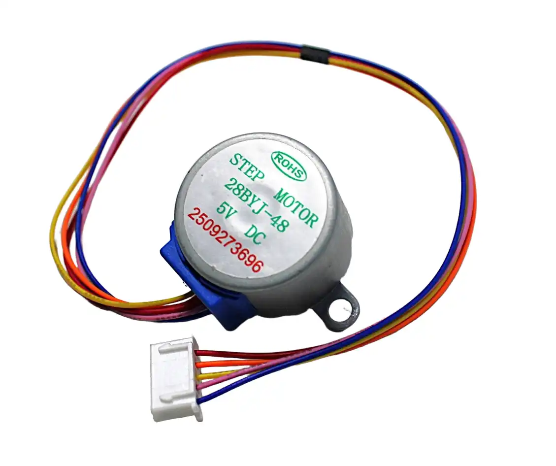
28BYJ-48 5V Stepper Motor
Compact unipolar stepper motor ideal for learning and low-torque projects. Uses ULN2003 driver (not A4988), making it a great introductory motor before moving to NEMA17 + A4988.
Common Mistakes & Fixes
Mistake 1: Measuring Vref with Motor Connected
When the motor is connected and energised, current flows through the sense resistors and slightly alters the Vref reading. Always measure Vref with the motor disconnected or the motor outputs disabled (ENABLE pin HIGH).
Mistake 2: Adjusting Vref While VMOT Is Disconnected
You need VMOT applied for the internal reference circuitry to function properly. Adjusting the pot without VMOT can give meaningless readings. Always power the board through both VDD and VMOT when setting Vref.
Mistake 3: Not Knowing the Rs Value
Using the formula with the wrong Rs gives completely wrong current settings. If you have cheap clone boards, measure the sense resistors directly. Many clone manufacturers use 0.1 Ω (R100) but some use 0.068 Ω or 0.05 Ω to support higher current ratings.
Mistake 4: Setting Vref Too High for Extended Runs
Running at 100% rated motor current on the A4988 causes the driver to thermal-shutdown during long prints or machining runs. Start at 80% of rated current and only increase if you experience missed steps.
Mistake 5: Skipping the Heat Sink
The A4988 without a heat sink in an enclosed enclosure can reach thermal shutdown within minutes at moderate currents. Always use the supplied heat sink and thermal adhesive tape.
Recommended Products from Zbotic
A4988 Stepper Motor Driver Controller Board – RED
Get the genuine Pololu-style A4988 driver board with heat sink, sense resistors marked R100 (0.1 Ω), and onboard Vref potentiometer. Delivered across India.
42HS48-1204A NEMA17 5.6 kg-cm Stepper Motor
High-quality NEMA17 motor with 1.2A rated current per phase. D-type shaft for secure coupling. Ideal for CNC and 3D printer X/Y/Z axes.
Frequently Asked Questions
What happens if I set Vref too high on the A4988?
Setting Vref too high forces more current through the motor coils than they are rated for. This causes excessive motor heating, premature driver thermal shutdown, and in extreme cases can burn out the motor windings or the A4988 IC itself. Always start with a conservative Vref and increase gradually.
Can I set Vref with the motor connected?
It is not recommended. With the motor energised, current through the sense resistors slightly shifts the Vref reading. For accurate calibration, disconnect the motor (or pull the ENABLE pin HIGH to disable outputs), set Vref, then reconnect and test.
My motor gets hot even at low current. Is that normal?
Stepper motors are designed to run warm — up to 80°C casing temperature is acceptable for most motors. However, if you cannot hold your hand on the motor for more than 2–3 seconds, the current is likely too high. Also check that the motor is not stalled (driving against a hard stop) which dramatically increases heating.
What is the difference between A4988 and DRV8825?
The DRV8825 is a higher-current alternative supporting up to 2.2 A per coil and 1/32 microstepping. Its Vref formula uses a different multiplier: I = Vref / 2 (with its internal 5 V reference). The A4988 is better for small motors under 1.5 A, while DRV8825 suits larger NEMA17 or NEMA23 motors.
Do I need to set Vref for the 28BYJ-48 stepper motor?
No. The 28BYJ-48 is a unipolar stepper motor typically driven by the ULN2003 driver board, not the A4988. The ULN2003 does not have a Vref setting — it drives the motor directly from the supply voltage. The A4988 Vref procedure applies only to bipolar stepper motors like NEMA17.
Why does my motor lose steps at high speeds even with correct Vref?
Step loss at high speeds is usually a back-EMF issue, not a current issue. As stepper motor speed increases, the impedance of the motor coil increases and the driver has less time to ramp up current to the Vref level per step. Using a higher VMOT voltage (e.g., 24 V instead of 12 V) improves high-speed torque. Also consider switching to the DRV8825 with a higher VMOT supply.
Conclusion
Setting the A4988 Vref correctly is a simple but critical step that directly determines how well your stepper motor performs and how long your driver lasts. The formula is straightforward: Vref = Imotor × 8 × Rs. Find your motor’s rated current, identify your board’s sense resistor value, calculate the target voltage, and adjust the pot while monitoring with a multimeter.
Start conservative — around 80% of rated current — and test. Add a heat sink, consider active cooling in enclosed builds, and use idle current reduction where your firmware supports it. With the right Vref, your NEMA17 or other bipolar stepper will run smoothly, quietly, and reliably for thousands of hours.
Ready to build? Pick up an A4988 driver board and a NEMA17 stepper motor from Zbotic and get your motion project running today.


Add comment