
The SPI communication protocol is one of the most widely used serial interfaces in embedded electronics. If you have ever connected a TFT display, an SD card module, or a digital potentiometer to an Arduino or ESP32, you have already used SPI — even if you did not realise it. This master-slave wiring tutorial breaks down everything from signal lines to multi-device configurations, with practical examples you can try on your own workbench today.
Table of Contents
- What is SPI?
- SPI Signal Lines Explained
- Master-Slave Wiring Diagram
- SPI Clock Polarity and Phase (CPOL/CPHA)
- Connecting Multiple SPI Slaves
- SPI with Arduino: Practical Example
- Common Wiring Mistakes and How to Fix Them
- Frequently Asked Questions
What is SPI?
SPI stands for Serial Peripheral Interface. It was originally developed by Motorola in the 1980s and has since become a de facto standard for short-distance communication between a microcontroller (the master) and one or more peripheral devices (slaves). Unlike UART — which is asynchronous — SPI uses a shared clock signal generated by the master, making it a synchronous communication protocol.
SPI is a full-duplex protocol, meaning data flows simultaneously in both directions: from master to slave and from slave to master at the same time. This is one of its key advantages over I2C, which is half-duplex.
Typical SPI data rates range from a few hundred kHz to tens of MHz, making it far faster than I2C or UART for bulk data transfers. This speed advantage is why SPI is the protocol of choice for displays, flash memory, ADCs, DACs, and RF modules.
SPI Signal Lines Explained
A standard SPI bus uses four signal lines:
- SCLK (Serial Clock): Generated by the master. All slaves listen to this clock and synchronise their data transmission to it. The clock frequency is set by the master and determines the SPI speed.
- MOSI (Master Out Slave In): Data sent from the master to the slave travels on this line. Some manufacturers label this SDO (Serial Data Out) from the master’s perspective or SDI from the slave’s perspective.
- MISO (Master In Slave Out): Data sent from the slave back to the master travels on this line. Some devices label this SDI or SDO depending on perspective.
- CS / SS (Chip Select / Slave Select): Each slave has its own CS line, driven by the master. When the master pulls CS LOW, it activates that specific slave. This is how the master addresses individual devices on a shared SPI bus.
Note: In modern documentation, you may see MOSI renamed to COPI (Controller Out Peripheral In) and MISO renamed to CIPO (Controller In Peripheral Out) as industry moves away from master/slave terminology. The electrical behaviour is identical.
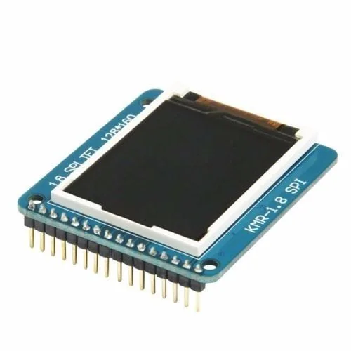
1.8 Inch SPI 128×160 TFT LCD Display Module for Arduino
A classic SPI device for hands-on learning. This TFT display uses the ST7735 driver and communicates entirely over SPI — great for practising master-slave wiring.
Master-Slave Wiring Diagram
For a single-slave SPI setup with an Arduino Uno as master, the connections are straightforward. Arduino Uno hardware SPI pins are:
- SCLK → Pin 13
- MISO → Pin 12
- MOSI → Pin 11
- SS (default) → Pin 10
Connect each of these to the corresponding pin on your slave device. Always also connect GND between the master and slave — a common ground is mandatory for reliable SPI communication. If the slave device runs on 3.3V logic and your Arduino is 5V, use a logic level converter on the MOSI, SCLK, and CS lines. MISO generally does not need conversion if the master GPIO is 5V tolerant, but check your microcontroller datasheet to be sure.
Wiring summary for Arduino Uno ↔ SPI slave:
| Arduino Uno Pin | SPI Signal | Slave Pin |
|---|---|---|
| 13 | SCLK | CLK / SCK |
| 12 | MISO | MISO / SDO |
| 11 | MOSI | MOSI / SDI |
| 10 | CS / SS | CS / CE / NSS |
| GND | GND | GND |

10CM Male To Male Breadboard Jumper Wires 2.54MM – 40Pcs
Colour-coded M-M jumper wires make SPI wiring on a breadboard clean and easy to trace. Assign one colour per SPI line to avoid wiring errors.
SPI Clock Polarity and Phase (CPOL/CPHA)
This is where beginners often get stuck. SPI defines four operating modes based on two parameters:
- CPOL (Clock Polarity): Defines the idle state of the clock. CPOL=0 means the clock is LOW when idle. CPOL=1 means the clock is HIGH when idle.
- CPHA (Clock Phase): Defines when data is sampled. CPHA=0 means data is sampled on the leading (first) clock edge. CPHA=1 means data is sampled on the trailing (second) clock edge.
These combine into four SPI modes:
| Mode | CPOL | CPHA | Common Use |
|---|---|---|---|
| 0 | 0 | 0 | Most common; SD cards, many ADCs |
| 1 | 0 | 1 | Some sensors and DACs |
| 2 | 1 | 0 | Less common |
| 3 | 1 | 1 | Some displays, ADXL345 |
Always check your slave device’s datasheet for the required SPI mode. Using the wrong mode means data will be read on the wrong clock edge and your communication will fail silently — a very common debugging trap.
In Arduino, set the SPI mode in your SPISettings object: SPISettings(8000000, MSBFIRST, SPI_MODE0) for Mode 0 at 8MHz with MSB sent first.
Connecting Multiple SPI Slaves
One of SPI’s great strengths is supporting multiple slaves on a single bus. There are two common approaches:
Independent CS lines (standard): Each slave shares SCLK, MOSI, and MISO lines but gets its own dedicated CS pin from the master. The master selects a slave by pulling its CS LOW. All other slaves have CS HIGH and ignore the bus traffic. This is the most reliable method and the one you should use by default.
Daisy-chaining: Some devices (shift registers like 74HC595, some ADCs) support daisy-chaining where MISO of one device connects to MOSI of the next. All devices share a single CS line and the master clocks data through the chain. This saves GPIO pins but requires all devices in the chain to be of the same type.
For the standard independent CS approach with three slaves, you need three GPIO pins for CS and still share the same three SCLK/MOSI/MISO lines. Plan your GPIO usage accordingly — the ESP32 has plenty of spare GPIOs, but the Arduino Uno’s 14 digital pins fill up quickly.
SPI with Arduino: Practical Example
Here is a minimal SPI transaction example using the Arduino SPI library to read a byte from a slave device:
#include <SPI.h>

const int CS_PIN = 10;

void setup() {
  Serial.begin(9600);
  SPI.begin();
  pinMode(CS_PIN, OUTPUT);
  digitalWrite(CS_PIN, HIGH); // Deselect slave initially
}

void loop() {
  SPI.beginTransaction(SPISettings(1000000, MSBFIRST, SPI_MODE0));
  digitalWrite(CS_PIN, LOW);         // Select slave
  byte received = SPI.transfer(0x00); // Send dummy byte, read response
  digitalWrite(CS_PIN, HIGH);        // Deselect slave
  SPI.endTransaction();

  Serial.println(received, HEX);
  delay(500);
}
The SPI.transfer() function simultaneously sends one byte and receives one byte — full duplex in action. For write-only devices (like many displays), you simply ignore the returned value. For read-only devices, you send a dummy 0x00 byte to generate the clock pulses needed for the slave to send its data.

10 x 10 cm Universal PCB Prototype Board Single-Sided 2.54mm
Once you have validated your SPI wiring on a breadboard, transfer it to this sturdy 10x10cm prototype PCB for a more permanent and reliable build.
Common Wiring Mistakes and How to Fix Them
- MISO and MOSI swapped: This is the single most common SPI wiring mistake. Remember: MISO on the master connects to MISO on the slave — not cross-wired like a UART TX-RX pair. Both call it by the same signal name from each device’s own perspective.
- Missing common ground: SPI signals are referenced to GND. If master and slave share no common ground, the voltage levels are meaningless. Always connect GND.
- Voltage mismatch: 5V Arduino MOSI driving a 3.3V slave MOSI pin can damage the slave over time. Use a level shifter or a resistor divider (for non-bidirectional lines).
- Wrong SPI mode: Check the datasheet. A device expecting Mode 3 will produce garbage output on Mode 0. The symptom is usually scrambled or all-zero/all-FF data.
- CS not released between transactions: Always drive CS HIGH after each transaction. Some devices will not reset their internal state machine until CS goes HIGH.
- Clock speed too high: Long breadboard wires and parasitic capacitance limit reliable SPI speeds. Start at 1MHz on a breadboard and only increase speed on a PCB with short traces.

10CM Male To Female Breadboard Jumper Wires 2.54MM – 40Pcs
Colour-coded M-F wires are ideal for connecting Arduino header pins directly to module pins. 40 pieces to cover all your SPI lines and then some.
Frequently Asked Questions
What is the maximum speed of SPI communication?
SPI has no defined maximum speed in the standard — it depends on the slave device and PCB trace quality. Common SPI speeds range from 1 MHz to 80 MHz. The ESP32 supports up to 80 MHz hardware SPI. On breadboards, keep speeds at or below 1-4 MHz to avoid signal integrity problems.
Can SPI work without the MISO line?
Yes. For write-only devices like many displays and LED drivers, you only need SCLK, MOSI, and CS. The MISO line can be left unconnected if you never need to read data back from the slave.
What is the difference between SPI and I2C?
SPI is faster (multi-MHz vs ~400 kHz for I2C), full-duplex, and does not require device addressing. However, SPI needs more wires (4 per device for CS) while I2C uses only 2 wires for many devices. I2C is better when you have many devices and limited pins; SPI is better when you need speed or bulk data transfer.
How many SPI slaves can I connect to one Arduino?
Theoretically unlimited, but practically limited by your available GPIO pins for CS lines. An Arduino Uno has 14 digital GPIO pins, so after allocating 3 for SPI bus lines and a few for other uses, you might manage 8-10 slaves. In practice, 2-4 SPI slaves on a single bus is common.
Why is my SPI device returning all 0xFF or all 0x00?
This usually means either the CS line is not being pulled LOW correctly (slave is not selected), MISO is not connected or is floating, the SPI mode is wrong, or the clock speed is too high. Check each of these systematically — start with CS, then mode, then speed.
—
Ready to build your first SPI project? Zbotic stocks all the components you need — SPI display modules, jumper wire packs, prototype PCBs, and development boards. Start experimenting today and experience the speed and simplicity of SPI communication. Browse components at Zbotic.in and get fast delivery across India.


Add comment