
Sound sensors open up a fascinating category of human-machine interaction. A light clap turns on a lamp. A sustained noise triggers a warning. A baby’s cry activates a monitor. All of these are achievable with a sub-₹100 sound pressure sensor module and an Arduino. In this comprehensive guide, you will build two complete projects — a clap switch and a noise meter with dB readings — while learning the physics of sound pressure, sensor selection, and signal processing techniques that apply far beyond these specific projects.
Sound Pressure Level Physics
Sound is a pressure wave — alternating compressions and rarefactions propagating through air. Sound Pressure Level (SPL) is measured in decibels (dB), a logarithmic scale referenced to 20 μPa (the threshold of human hearing):
SPL (dBSPL) = 20 × log₁₀(P / P_ref)
where P = measured pressure, P_ref = 20 μPa
The logarithmic nature means each 10 dB increase represents a 10× increase in sound intensity, and each 20 dB increase is a 10× increase in pressure amplitude. Key reference points:
- 0 dBSPL: threshold of hearing
- 30 dBSPL: quiet bedroom
- 60 dBSPL: normal conversation
- 85 dBSPL: sustained damage threshold
- 120 dBSPL: threshold of pain
- 140 dBSPL: jet engine at 5 m
A hand clap at 1 m produces roughly 60–80 dBSPL depending on hand size and technique. This is well within the range of standard microphone sensor modules.
Types of Sound Sensor Modules
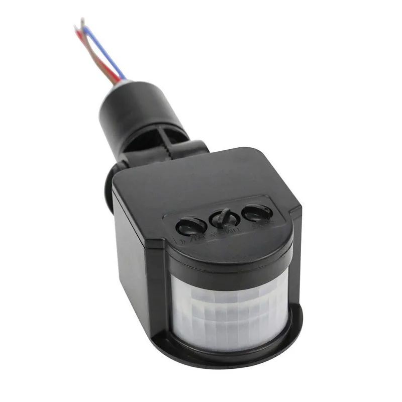
Basic Microphone Breakout (DO + AO)
The most common beginner sound module uses an electret microphone capsule with a simple LM393 comparator circuit. It provides:
- DO (Digital Output): Goes HIGH when sound exceeds a threshold set by an onboard potentiometer. Used for clap switches and alarm triggers.
- AO (Analog Output): Raw AC waveform from the microphone, biased to VCC/2. Used for amplitude measurement and noise metering.
Supply voltage: typically 3.3–5V. Sensitivity: adjustable via potentiometer. Microphone frequency response: 20 Hz – 20 kHz (flat-ish in mid-range). Price: ₹40–100.
MAX4466 / MAX9814 Amplified Microphone Modules
These use dedicated microphone amplifier ICs with automatic gain control (AGC — MAX9814) or fixed gain (MAX4466). They output a cleaner, better-amplified analog signal, making them more suitable for frequency analysis and speech detection. Price: ₹150–350.
MEMS Digital Microphone (I2S)
High-end projects (voice recognition, audio recording) use MEMS microphones with I2S digital output (INMP441, SPH0645). These output 24-bit digital audio data at up to 44 kHz sample rate. Requires I2S-capable microcontrollers (ESP32, STM32). Beyond the scope of this beginner-to-intermediate guide, but worth knowing for future projects.
Hardware Setup
Components Needed
- Arduino Uno (or Nano, Mega)
- Sound sensor module with DO and AO pins
- 5 mm LED + 220Ω resistor (clap switch output indicator)
- Optional: relay module for controlling real AC devices
- Optional: OLED 128×64 I2C display (noise meter display)
- Breadboard and jumper wires
Wiring Diagram
Sound Sensor → Arduino Uno
VCC          → 5V
GND          → GND
DO           → D7 (digital input, use INPUT_PULLUP or not as needed)
AO           → A0 (analog input)

LED Indicator:
D → 220Ω → LED anode → LED cathode → GND
Arduino D13 → 220Ω resistor → LED

Relay Module (optional, for mains-connected loads):
IN           → D8 (Arduino digital out)
VCC          → 5V
GND          → GND
NO/NC/COM    → AC load (with proper safety enclosure)
Sensitivity Adjustment
Before coding, adjust the potentiometer on the sound module. Set it so the DO LED on the module stays OFF in ambient noise but turns ON when you clap directly in front of the microphone from 30 cm. This is the threshold for your clap switch. A small flat-head screwdriver or trimmer is needed to rotate the potentiometer. Clockwise typically increases sensitivity on most modules.
Project 1: Clap Switch
The simplest clap switch toggles a LED (or relay) every time a loud sound pulse is detected on the DO pin. We track the toggle state in a boolean variable.
const int SOUND_DO_PIN = 7;
const int LED_PIN = 13;
bool ledState = false;
bool lastSoundState = LOW;

void setup() {
  Serial.begin(9600);
  pinMode(SOUND_DO_PIN, INPUT);
  pinMode(LED_PIN, OUTPUT);
  digitalWrite(LED_PIN, LOW);
}

void loop() {
  bool soundDetected = (digitalRead(SOUND_DO_PIN) == HIGH);

  if (soundDetected && !lastSoundState) {
    // Rising edge detected — clap!
    ledState = !ledState;
    digitalWrite(LED_PIN, ledState ? HIGH : LOW);
    Serial.println(ledState ? "Light ON" : "Light OFF");
    delay(300); // debounce: ignore retriggering for 300ms
  }

  lastSoundState = soundDetected;
}
Test it: single clap turns the LED on, second clap turns it off. The 300 ms delay prevents the echo or reverberation of one clap from triggering multiple toggles. This delay is a simple but effective debounce for this use case.
Handling False Triggers and Debouncing
The simple 300 ms delay debounce works but blocks execution. In a project with other sensors, this is problematic. Here is a non-blocking debounce using millis():
const int SOUND_DO_PIN = 7;
const int LED_PIN = 13;
bool ledState = false;
unsigned long lastClapTime = 0;
const unsigned long CLAP_DEBOUNCE_MS = 300;

void setup() {
  Serial.begin(9600);
  pinMode(SOUND_DO_PIN, INPUT);
  pinMode(LED_PIN, OUTPUT);
}

void loop() {
  if (digitalRead(SOUND_DO_PIN) == HIGH) {
    unsigned long now = millis();
    if (now - lastClapTime > CLAP_DEBOUNCE_MS) {
      lastClapTime = now;
      ledState = !ledState;
      digitalWrite(LED_PIN, ledState);
      Serial.println(ledState ? "ON" : "OFF");
    }
  }
  // Other sensor code can run here without blocking
}
Handling Ambient Noise
In noisy environments (kitchen, workshop) ambient sounds may keep the DO pin HIGH intermittently. Solutions:
- Increase threshold: Turn the potentiometer towards lower sensitivity until only loud impacts (claps, knocks) trigger it.
- Pulse duration check: Claps are brief (<100 ms). Ambient noise often triggers shorter or longer pulses. Read DO repeatedly in a tight loop for 80 ms; only act if the pulse ends within that window.
- Double-clap pattern: Require two claps within 800 ms (see Advanced section below) — accidental triggers from random loud sounds are far less likely to match the pattern.
Project 2: Noise Meter in dB
For a noise meter, we use the AO (analog output) pin, which provides the raw microphone waveform. The technique: sample many readings over a window (50–100 ms), compute the peak-to-peak voltage swing, then map that to a dBSPL estimate.
Why Peak-to-Peak?
The microphone output is an AC signal centred on VCC/2 (~2.5V). At silence, all readings are ~512 (on 10-bit ADC). A loud sound swings the ADC reading up and down from this centre. Peak-to-peak amplitude correlates with sound pressure amplitude, and from amplitude we derive SPL using the decibel formula.
const int SOUND_AO_PIN = A0;
const int SAMPLE_WINDOW_MS = 50; // sample for 50ms
const float MIC_SENSITIVITY = 0.00631;  // adjust during calibration
const float P_REF = 0.00002; // 20 microPascals

float readSPL() {
  unsigned long startTime = millis();
  int maxVal = 0, minVal = 1023;
  while (millis() - startTime < SAMPLE_WINDOW_MS) {
    int sample = analogRead(SOUND_AO_PIN);
    maxVal = max(maxVal, sample);
    minVal = min(minVal, sample);
  }
  float peakToPeak = maxVal - minVal;         // ADC counts
  float voltage_pp = peakToPeak * (5.0 / 1023.0); // Volts
  float pressure = voltage_pp * MIC_SENSITIVITY;   // Pascals (approx)
  if (pressure < P_REF) pressure = P_REF;    // clamp to avoid log(0)
  return 20.0 * log10(pressure / P_REF);     // dBSPL
}

void setup() { Serial.begin(115200); }

void loop() {
  float spl = readSPL();
  Serial.print("SPL: ");
  Serial.print(spl, 1);
  Serial.println(" dB");
}
The MIC_SENSITIVITY constant converts ADC voltage swing to pascals. This requires calibration (see below). Without calibration, you will get a relative dB reading that is internally consistent but may be offset from true dBSPL by 5–20 dB.
Adding an OLED or LCD Display
A noise meter is much more useful with a visual display. Here is the OLED integration using the Adafruit SSD1306 library:
#include <Wire.h>
#include <Adafruit_GFX.h>
#include <Adafruit_SSD1306.h>

#define SCREEN_W 128
#define SCREEN_H 64
Adafruit_SSD1306 display(SCREEN_W, SCREEN_H, &Wire, -1);

void setup() {
  display.begin(SSD1306_SWITCHCAPVCC, 0x3C);
  display.clearDisplay();
}

void loop() {
  float spl = readSPL(); // function from above
  display.clearDisplay();
  display.setTextSize(2);
  display.setTextColor(SSD1306_WHITE);
  display.setCursor(0, 10);
  display.print(spl, 1);
  display.println(" dB");
  // Draw a simple bar graph
  int barWidth = map(constrain((int)spl, 30, 100), 30, 100, 0, 128);
  display.fillRect(0, 45, barWidth, 12, SSD1306_WHITE);
  display.display();
}
Wire the OLED: VCC→3.3V, GND→GND, SCL→A5, SDA→A4. The bar graph gives instant visual feedback on noise level, making this a genuinely useful workplace noise monitor.
Calibrating Your Noise Meter
For calibrated dBSPL readings, you need a reference source. Two practical approaches:
Method 1: Phone App Reference
- Install a trusted SPL meter app on your phone (NIOSH SLM, Decibel X — both are well-regarded).
- Place your Arduino sensor and your phone microphone side-by-side, same height, pointing the same direction.
- Play a 1 kHz tone at a fixed volume from a speaker 1 m away (use a tone generator app or website).
- Note the phone app reading (e.g., 65 dBSPL) and your Arduino reading (e.g., 52 dB uncalibrated).
- The difference (13 dB in this example) is your calibration offset: add it to every reading, or adjust
MIC_SENSITIVITYuntil readings match.
Phone apps themselves may be ±3 dB accurate — this is sufficient for most DIY noise meter applications (workplace assessment, party noise complaints, industrial safety awareness).
Method 2: Adjust MIC_SENSITIVITY Constant
At 65 dBSPL, the RMS pressure is 0.0356 Pa. If your ADC peak-to-peak at that SPL is, say, 200 counts (0.977V), then RMS voltage ≈ 0.977/2.83 = 0.345V. Sensitivity = 0.345V / 0.0356Pa = 9.69 mV/Pa. Update MIC_SENSITIVITY = 0.00969. Repeat across 3–4 SPL levels and average the constant for best accuracy.
After calibration, a well-built Arduino noise meter with a good microphone module achieves ±3–5 dB accuracy — adequate for workplace safety awareness, classroom noise control, and HVAC equipment monitoring.
Advanced: Double-Clap Pattern Recognition
A single-clap switch is prone to false triggers. A double-clap (two claps within 0.8 seconds) is a much more distinctive human gesture. Here is a state machine implementation:
// Double-clap state machine
const unsigned long CLAP_MAX_GAP_MS = 800;  // max ms between clap 1 and clap 2
const unsigned long CLAP_MIN_GAP_MS = 100;  // min ms gap (reject stutters)
const unsigned long DEBOUNCE_MS = 80;

enum ClapState { IDLE, FIRST_CLAP };
ClapState state = IDLE;
unsigned long firstClapTime = 0;
unsigned long lastTriggerTime = 0;
bool lightOn = false;

void handleSound() {
  unsigned long now = millis();
  if (now - lastTriggerTime < DEBOUNCE_MS) return;
  lastTriggerTime = now;

  if (state == IDLE) {
    state = FIRST_CLAP;
    firstClapTime = now;
  } else if (state == FIRST_CLAP) {
    unsigned long gap = now - firstClapTime;
    if (gap >= CLAP_MIN_GAP_MS && gap <= CLAP_MAX_GAP_MS) {
      // Valid double clap!
      lightOn = !lightOn;
      digitalWrite(13, lightOn);
      Serial.println(lightOn ? "DOUBLE CLAP: ON" : "DOUBLE CLAP: OFF");
    }
    state = IDLE;
  }
}

void loop() {
  // Reset state if first clap was too long ago
  if (state == FIRST_CLAP && millis() - firstClapTime > CLAP_MAX_GAP_MS) {
    state = IDLE;
  }
  if (digitalRead(7) == HIGH) handleSound();
}
This pattern recognizer fires the toggle only when two claps land within the 100–800 ms window. A single loud bang, a door slam, or a sustained noise will not match the pattern. For even more robustness, add a third-clap requirement or use the AO analog channel to verify the sharp amplitude spike characteristic of a hand clap versus a sustained sound.
Real-World Applications
Smart Home Integration
Replace the LED output with a relay module and you can control any AC device (fan, lamp, TV) with a clap. For safety, always use an optically isolated relay module rated for the AC voltage in your circuit, and enclose all mains wiring in a proper enclosure. Never work on mains wiring unless you are qualified and confident. The relay module itself is Arduino-safe — its input side is 5V DC.
Industrial Noise Monitoring
Deploy multiple noise meters on a factory floor, each with an ESP8266/ESP32, reporting readings via MQTT to a central dashboard (Home Assistant, Node-RED, or a custom web server). Log readings to SD card or cloud. Trigger alerts when SPL exceeds 85 dB for more than 8 minutes per OSHA guidelines. The cost of such a multi-zone industrial noise monitoring system using Arduino components is under ₹3,000 per node versus ₹15,000–50,000 for commercial data-logging sound level meters.
Baby / Pet Sound Monitor
Set the threshold at ~60 dB — typical crying or barking. Trigger an SMS via an ESP8266 + Twilio API or an LED/buzzer in another room. Unlike commercial baby monitors, your DIY version has no monthly subscription, stores data locally, and can be customised for specific threshold patterns.
Handclap-Controlled Presentation Remote
An Arduino Leonardo (with native USB HID) can emulate a keyboard. A single clap sends a right-arrow keypress (next slide), a double-clap sends left-arrow (previous slide). Pair this with a Bluetooth module (HC-05) and you have a completely wireless, gesture-controlled presentation remote with no battery in the remote itself — just a BLE module on a wristband or in your pocket.
Acoustic Event Logger
Record peak SPL every second to an SD card with timestamp (using a DS3231 RTC module). Plot the data in Excel or Python to build a 24-hour acoustic profile of a room — useful for office noise complaints, construction site compliance documentation, or sleep disturbance analysis.
Recommended Products from Zbotic

LM35 Temperature Sensor
Add temperature sensing alongside your noise meter for a combined environmental monitor — both use analog signals and work with the same Arduino sketch structure.

GY-BME280 3.3V Precision Altimeter Atmospheric Pressure Sensor
Combine with your sound sensor for a complete environmental data logger — temperature, humidity, pressure and noise level from a single Arduino.
AC 220V PIR Human Body Motion Sensor Detector LED Light Switch
Combine with your clap switch project — motion detection activates the relay first, clap switch overrides it. Dual-mode smart lighting control.

MQ-135 Air Quality / Gas Detector Sensor Module
Build a full indoor environment monitor: the MQ-135 adds CO2 and smoke detection alongside your noise meter on the same Arduino OLED dashboard.

INA219 I2C Bi-directional Current / Power Monitoring Module
Add power measurement to your smart home automation system — monitor exactly how much energy your relay-switched devices consume.
Frequently Asked Questions
Why does my clap switch sometimes turn on by itself?
False triggers are caused by ambient sounds exceeding the threshold — a door slam, a chair scraping, a TV at high volume. Solutions in order of effectiveness: (1) Increase the DO threshold by turning the potentiometer towards lower sensitivity; (2) Add a 300 ms debounce; (3) Implement double-clap pattern recognition; (4) Use the AO analog output with peak duration measurement to distinguish a sharp clap impulse from sustained ambient noise.
Can I use this to control AC lights safely?
Yes, if done correctly. Use an opto-isolated relay module (not a bare transistor output). The relay module’s input side is isolated from its output side — the 5V Arduino control circuit is physically separated from the 230V AC load circuit. Enclose all AC wiring in a plastic junction box with no exposed metal parts. Use wire rated for the current of the lamp. Never work on a live circuit. If you are not confident with AC wiring, use a 5V DC LED strip or a USB-powered device as a safer alternative for learning.
My noise meter reads 40 dB even in a silent room. Is this correct?
A truly silent room is around 20–30 dBSPL. A typical quiet room has ambient noise of 30–45 dBSPL from HVAC, traffic, and building sounds. 40 dB in a quiet room is not unusual or incorrect. If you are getting 40 dB in an anechoic chamber or acoustically dead space, the sensor’s own electronic noise floor is approximately at that level — which is normal for inexpensive electret microphone modules.
Can I measure frequency (pitch) with this sensor?
Yes, using the AO output and Arduino’s analogRead at maximum speed, you can sample at ~10 kHz (limited by ADC conversion time). This is enough to capture audio up to 5 kHz (Nyquist theorem). Use an FFT library (ArduinoFFT) to convert the sampled waveform into a frequency spectrum. The result is a basic spectrum analyser — you can detect dominant frequencies and distinguish bass from treble. For voice recognition or music analysis, upgrade to ESP32 with its built-in 12-bit ADC capable of 2 MSPS and use the I2S MEMS microphone for better quality.
What is the range of a microphone module — how far away can it detect a clap?
Sound pressure follows the inverse square law: doubling the distance quarters the intensity (-6 dB). A hand clap at 1 m produces ~70 dBSPL. At 3 m it drops to ~60 dBSPL. Most microphone modules can reliably trigger at 60+ dBSPL, so detection range for a typical hand clap in a quiet room is 2–4 m. In a noisy environment (kitchen, street traffic at 60–70 dB ambient), the signal-to-noise ratio drops and reliable detection range shrinks to under 1 m unless you raise the clap volume significantly.
Shop Zbotic’s sensors and measurement modules for everything you need — microphone modules, relay boards, display modules, and complete Arduino starter kits. Free shipping above ₹999 with same-day dispatch.


Add comment