
If you have ever wondered why your oscilloscope waveform looks distorted or your high-frequency signal appears rounded at the edges, the answer almost certainly lies in your oscilloscope probe 1x 10x compensation settings. Choosing the right probe attenuation and performing proper compensation is one of the most overlooked skills in electronics debugging — yet it has a dramatic impact on measurement accuracy. This guide covers everything you need to know, from the physics of probe loading to step-by-step compensation procedures.
What Is an Oscilloscope Probe?
An oscilloscope probe is the physical interface between your circuit under test and the oscilloscope input. It looks deceptively simple — a pointed tip, a coaxial cable, a BNC connector, and a ground clip. However, the probe is an active participant in the measurement chain. It contributes its own resistance, capacitance, and inductance that can alter the very signal you are trying to observe.
Modern oscilloscope probes are designed to present the lowest possible loading to the circuit while still delivering an accurate replica of the signal to the scope input. The two most common types found in hobbyist and professional labs alike are the 1x (unity gain) probe and the 10x (attenuating) probe. Understanding the difference between these two is fundamental to getting reliable readings.
Most budget oscilloscopes sold in India ship with a dual-mode probe that can switch between 1x and 10x using a small slider near the probe tip. While convenient, these sliding switches can develop intermittent contact over time, which is a common source of puzzling measurement errors.
1x vs 10x Probes: Key Differences
The number before the “x” tells you the attenuation ratio of the probe. A 1x probe passes the signal through to the scope at full amplitude. A 10x probe divides the signal by 10 before it reaches the scope input, and the scope compensates by multiplying its displayed reading by 10.
Electrical Characteristics
| Parameter | 1x Probe | 10x Probe |
|---|---|---|
| Input Resistance | 1 MΩ (same as scope) | 10 MΩ (9 MΩ in probe + 1 MΩ scope) |
| Input Capacitance | ~100 pF (higher) | ~10–20 pF (much lower) |
| Bandwidth | Typically 6–10 MHz | Typically 100–300 MHz |
| Signal Loss | None (full amplitude) | 10:1 attenuation (corrected by scope) |
| Best For | Low-frequency, small signals | High-frequency, general purpose |
The dramatic difference in input capacitance is the critical insight. A 1x probe has roughly 100 pF of input capacitance, which forms an RC low-pass filter with the source impedance of your circuit. At high frequencies, this filter starts attenuating your signal — producing the rounded edges and amplitude errors you may have observed. The 10x probe’s ~15 pF capacitance is nearly transparent to signals up into the hundreds of megahertz range.
When to Use 1x and When to Use 10x
Knowing which probe setting to select saves you hours of debugging frustration. Here is a practical decision framework:
Use 1x Probes When:
- Signal amplitude is very small (under 50 mV peak-to-peak) — the 10x attenuation would push small signals below your scope’s noise floor
- Frequency is below 1 MHz — at these frequencies, the high capacitance of a 1x probe has negligible effect on the waveform
- You are measuring audio circuits — audio bandwidth (20 Hz to 20 kHz) is well within 1x probe capability
- Checking slow DC transients — power rail startup sequences, battery voltage curves
Use 10x Probes When:
- Working with microcontrollers and digital logic — clock edges, SPI/I2C/UART waveforms benefit from 10x bandwidth
- Measuring switching power supplies — PWM waveforms, gate drive signals, inductor current waveforms
- RF or high-speed signals above 1 MHz — always use 10x for anything above a few MHz
- High-impedance circuits — 10x probe’s 10 MΩ loading is much kinder to sensitive analog stages
- General-purpose everyday use — when in doubt, use 10x
A common mistake among beginners is leaving the probe on 1x permanently because “the signal looks bigger.” This seems helpful until you realise the rounded edges on your 10 MHz clock signal are not ringing — they are simply the probe’s own bandwidth limitation hiding the real shape of the waveform.
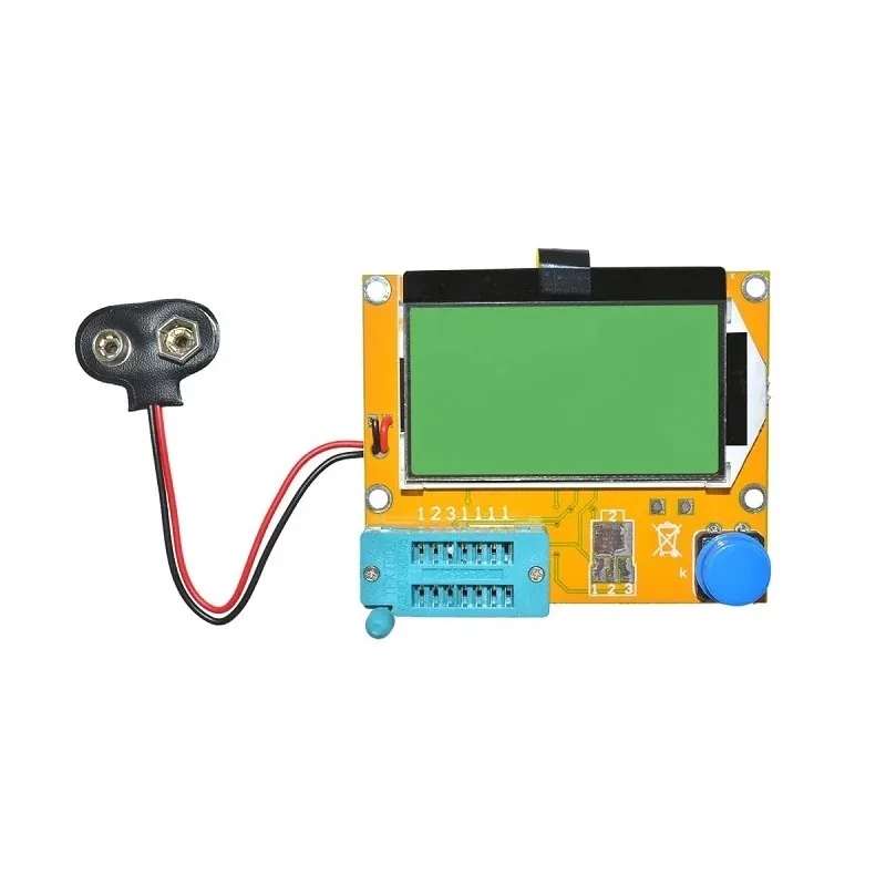
LCR-T4 Graphical Transistor & Component Tester
Quickly verify capacitors, resistors, transistors, and ESR values before connecting them to your test circuit. Essential companion tool alongside your oscilloscope for component-level debugging.
Understanding Probe Loading Effects
Probe loading is the phenomenon where connecting your probe actually changes the circuit’s behaviour. Even a 10x probe with its 10 MΩ resistance and 15 pF capacitance can significantly disturb high-impedance circuits or resonant circuits like LC oscillators.
Resistive Loading
If your circuit has a source impedance of 1 kΩ and you attach a 10x probe (10 MΩ), the loading effect is 1 kΩ / (1 kΩ + 10 MΩ) = 0.01% — completely negligible. But if your circuit source impedance is 500 kΩ (common in precision analog circuits), that 10 MΩ probe creates a voltage divider causing a 5% measurement error even before frequency effects are considered.
Capacitive Loading
The 15 pF capacitance of a 10x probe in parallel with a 100 kΩ source gives a corner frequency of 1/(2π × 100k × 15p) = 106 kHz. Above this frequency, your measurement starts attenuating. For a 1x probe with 100 pF, the same source gives a corner of just 16 kHz — audio frequency! This is why 1x probes are fundamentally unsuitable for anything above a few tens of kilohertz when working with moderate source impedances.
Ground Lead Inductance
The ground clip and its lead add significant inductance — often 20–150 nH depending on length. This inductance resonates with the probe tip capacitance to produce the classic “pig-tail” ringing seen on fast edges when using a long ground lead. Always use the shortest possible ground connection. Most quality probes include short ground springs or alligator clips specifically designed for this purpose.
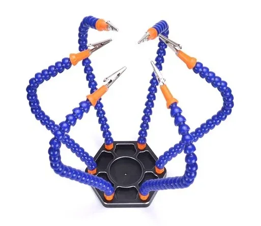
6-Arm Flexible Soldering Station with Alligator Clips
Hold PCBs and components steady while probing with your oscilloscope. The swiveling alligator clips let you clamp the ground clip close to the measurement point — critical for minimising ground loop inductance.
How to Compensate Your Oscilloscope Probe
Probe compensation is the process of adjusting a small trimmer capacitor inside the probe body so that the probe’s frequency response is flat — meaning it passes all frequencies equally without high-frequency boost or rolloff. This adjustment is necessary because the scope’s input capacitance varies slightly from unit to unit, and the probe must be tuned to match its specific scope.
Why Compensation Matters
An uncompensated probe produces two failure modes:
- Over-compensated (too much capacitance): Square waves show overshoot and ringing at edges. High-frequency content appears boosted.
- Under-compensated (too little capacitance): Square wave edges appear rounded and slow. High-frequency content is attenuated, hiding fast transitions.
- Correctly compensated: Square wave shows perfectly flat tops and bottoms with clean vertical edges (within the probe’s bandwidth).
Step-by-Step Compensation Procedure
- Locate the calibration output — nearly every oscilloscope has a small pin or pad on the front panel labelled “CAL” or “PROBE COMP.” It outputs a 1 kHz square wave at a precise 1V or 3.3V amplitude.
- Set the probe to 10x — compensation is only meaningful for 10x probes. Make sure your scope’s channel input setting also shows 10x.
- Connect the probe tip to CAL, ground clip to GND — keep the ground lead short.
- Set the scope timebase to 200 µs/div and voltage scale to 500 mV/div — this makes the 1 kHz square wave clearly visible.
- Observe the square wave top — is it flat, does it dip in the middle (under-compensated), or does it peak at the edges (over-compensated)?
- Adjust the trimmer — use a non-metallic trimmer tool (usually supplied with the probe or scope) to turn the small slotted adjustment on the probe body. Turn slowly and watch the waveform change in real time.
- Stop when tops and bottoms are perfectly flat — this indicates correct compensation.
- Repeat for every probe on every scope — probes are not interchangeable without re-compensation.
Pro tip: Re-compensate any time you change the scope’s input settings (e.g., from AC to DC coupling changes the input RC slightly on some scopes), after shipping the scope, or after any physical shock.
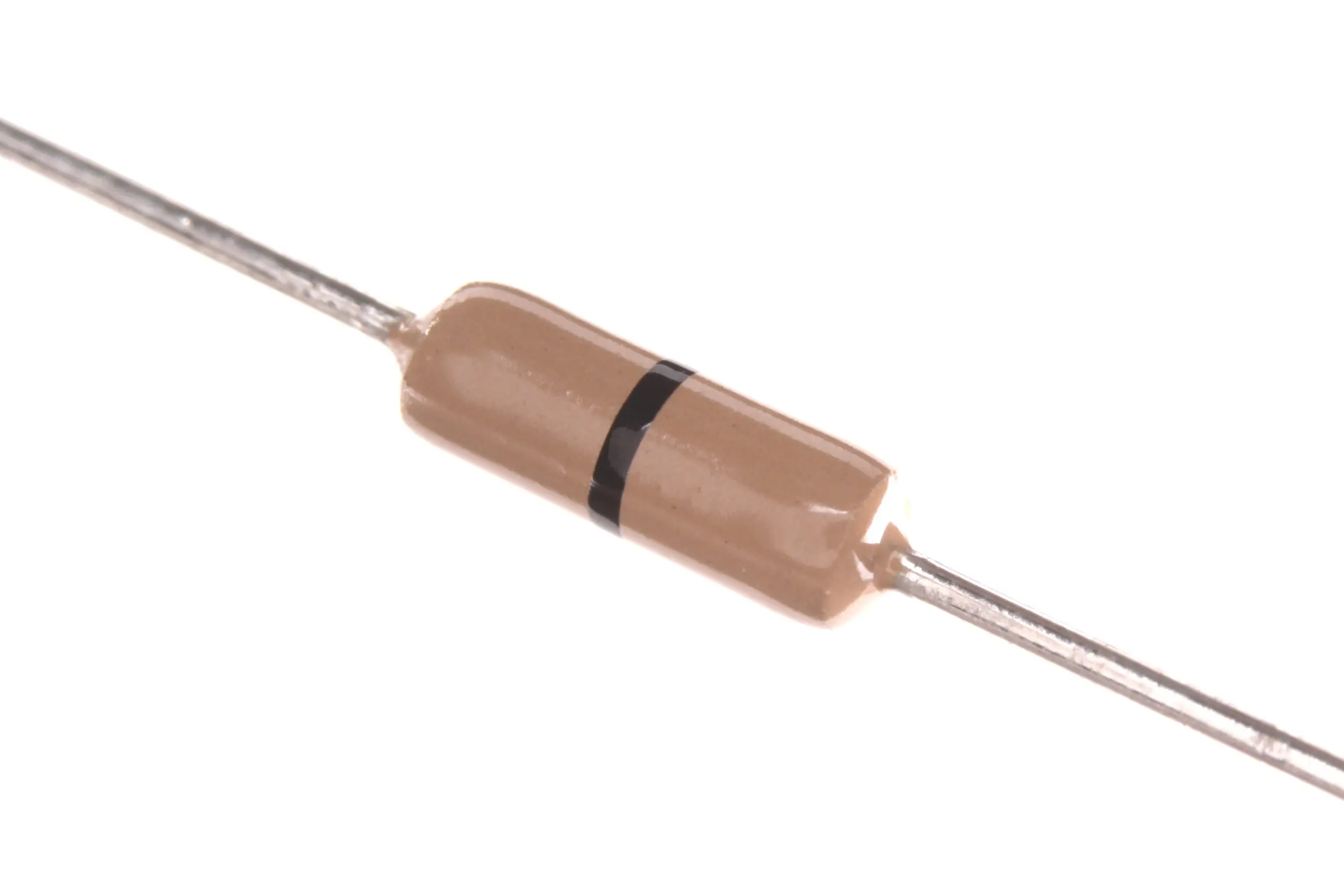
0 Ohm 0.25W Carbon Film Resistors (Pack of 100)
Use zero-ohm jumpers as convenient probe test points on your prototype boards, making it easy to clip your ground lead right next to the signal you are measuring for cleaner, lower-inductance measurements.
Common Probe Mistakes and How to Avoid Them
1. Scope Set to 1x, Probe Set to 10x (or Vice Versa)
This mismatch means the scope’s displayed amplitude is wrong by a factor of 10. Always verify that both the probe’s physical setting and the scope’s channel configuration agree. Modern scopes detect probe attenuation automatically via a resistor coded into the BNC connector — but older or budget scopes require manual input.
2. Long Ground Leads
The supplied 15–20 cm ground lead looks fine at audio frequencies but becomes a significant inductor at MHz frequencies. For any measurement above 1 MHz, use a short ground spring or wrap a bare wire around the probe barrel as a makeshift local ground. This single change can eliminate mysterious ringing that has nothing to do with your circuit.
3. Probing High-Voltage Circuits with Standard Probes
Standard 1x/10x probes are typically rated for 150–300V CAT II. Measuring mains-related circuits or motor drives requires high-voltage differential probes rated for the appropriate CAT III/IV category. Never exceed your probe’s rated voltage.
4. Ignoring Probe Bandwidth vs Scope Bandwidth
A 100 MHz oscilloscope paired with a 60 MHz probe gives you a 60 MHz system. The probe is always the bottleneck. When purchasing replacement probes, always match or exceed your scope’s rated bandwidth.
5. Probing Moving or Vibrating Boards Without Securing the Ground
When the ground clip bounces against an adjacent pad, it creates large noise spikes that look like genuine signal content. Secure both the probe tip and ground before trusting any waveform.
Buying Oscilloscope Probes and Test Accessories in India
Good test equipment starts with reliable accessories. If you are building a home lab in India, here are the essentials beyond the oscilloscope itself:

10cm Male to Female Jumper Wires (40 Pcs)
Use these jumper wires to create accessible test points on breadboard prototypes, making it much easier to position your oscilloscope probe accurately without disturbing fragile breadboard connections.
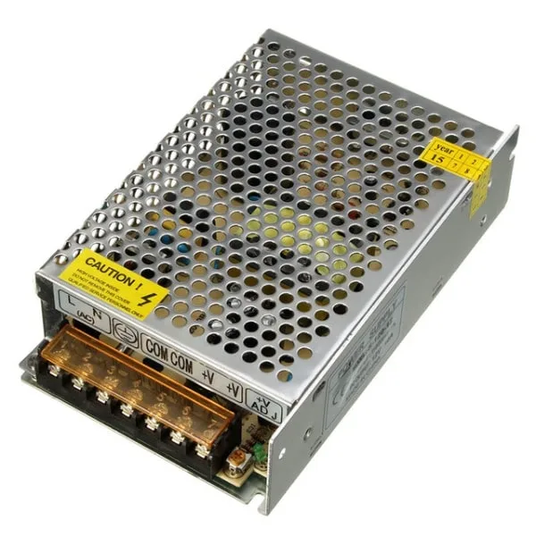
12V 10A SMPS 120W Metal Power Supply
A stable bench power supply is as important as the oscilloscope itself. Use this 12V SMPS to power your DUT (device under test) while keeping the power rail isolated from mains noise that could corrupt measurements.
Frequently Asked Questions
What happens if I use a 1x probe setting on my oscilloscope for a high-frequency signal?
The high input capacitance (~100 pF) of a 1x probe acts as a low-pass filter that attenuates high-frequency content. On signals above a few MHz, you will see rounded edges, reduced amplitude, and distorted waveform shapes that do not reflect the true signal in your circuit. For anything above 1 MHz, always use the 10x setting.
How often should I compensate my oscilloscope probes?
Compensate every time you connect a probe to a different oscilloscope, after any physical shock or transport, and at the start of each important measurement session. Temperature changes in the lab can also shift compensation slightly, so a quick check at the start of the day is good practice.
Can I use the same probe on different oscilloscopes?
Yes, but you must re-compensate the probe each time you switch scopes. The input capacitance varies between different oscilloscope models and even between channels on the same scope, so the trimmer setting for one scope will likely be wrong for another. Always re-run the compensation procedure on the calibration output of the new scope.
My square wave on the CAL output shows ringing — is the probe faulty?
Not necessarily. Ringing on square wave edges (especially at 1 kHz on the CAL output) is usually caused by a long ground lead creating a ground loop. Shorten the ground connection to the bare minimum and the ringing will typically disappear. If ringing persists with a short ground, the probe may be over-compensated — turn the trimmer slightly to reduce it.
What is the bandwidth of a standard probe that comes with a budget oscilloscope in India?
Budget oscilloscopes sold in India (such as those in the ₹5,000–₹15,000 range) typically ship with probes rated for the same bandwidth as the scope — commonly 100 MHz in 10x mode and 6–10 MHz in 1x mode. If you need to measure signals faster than the probe’s rated bandwidth, you will need to purchase a higher-bandwidth probe separately, matched to your scope’s BNC specification and input impedance.
Ready to Upgrade Your Electronics Lab?
Now that you understand probe compensation and the 1x vs 10x difference, pair your oscilloscope with quality components and tools from Zbotic. We stock everything from component testers and power supplies to jumper wires and prototype boards — all shipped fast across India.


Add comment