
Every electronics hobbyist eventually encounters a frustrating problem: a clean digital signal that should toggle a circuit cleanly instead causes it to chatter, flicker, or oscillate erratically. The solution is almost always a Schmitt trigger circuit — a simple but powerful technique that adds hysteresis to comparators and logic gates, giving your circuits rock-solid noise immunity. Whether you’re reading a slow-changing sensor, debouncing a push button, or cleaning up a noisy waveform, understanding Schmitt triggers is an essential skill for any maker working with real-world signals in India’s electrically noisy environment.
Table of Contents
- What is a Schmitt Trigger?
- Hysteresis Explained: The Key Concept
- 74HC14 Schmitt Trigger IC: Pinout and Specs
- Building a Schmitt Trigger with Op-Amp
- Practical Circuit Applications
- Button Debouncing with Schmitt Trigger
- Schmitt Trigger Oscillator Circuit
- Frequently Asked Questions
What is a Schmitt Trigger?
A Schmitt trigger is a comparator circuit with positive feedback that creates two distinct switching thresholds — an upper threshold (VT+) for LOW-to-HIGH transitions, and a lower threshold (VT-) for HIGH-to-LOW transitions. This dual-threshold behaviour is called hysteresis.
Named after American scientist Otto Herbert Schmitt who described it in his 1938 PhD thesis, the Schmitt trigger solves one of the most fundamental problems in practical electronics: what happens when an input signal slowly or noisily crosses the switching threshold of a digital gate? A regular comparator switches erratically, producing multiple pulses. A Schmitt trigger switches cleanly, once, and stays switched — immune to small noise fluctuations around the threshold.
In India, where power supply quality varies widely and electromagnetic interference (EMI) from inverters, motors, and switching power supplies is common, Schmitt trigger circuits are not just useful — they’re often essential for reliable operation.
Hysteresis Explained: The Key Concept
Hysteresis is the property of a system where the output depends not just on the current input, but on the history of the input — specifically, which direction the input was last moving. Consider a thermostat: if the set point is 25°C, it turns on cooling at 26°C (upper threshold) and turns it off at 24°C (lower threshold), not both at 25°C. That 2°C gap is hysteresis.
For a Schmitt trigger, hysteresis works like this:
- If the input is LOW and rising, the output switches from HIGH to LOW only when the input crosses VT+ (upper threshold)
- If the input is HIGH and falling, the output switches from LOW to HIGH only when the input crosses VT- (lower threshold)
- The gap between VT+ and VT- is called the hysteresis window or hysteresis voltage (VH)
For the popular 74HC14 inverting Schmitt trigger operating at 5V: VT+ ≈ 2.4V, VT- ≈ 1.2V, giving VH ≈ 1.2V. Any noise smaller than 1.2V amplitude that sits between the two thresholds causes no output change — perfect noise rejection.
The input-output relationship of a Schmitt trigger on a graph looks like a rectangular hysteresis loop — wider loops mean greater noise immunity but slower response to legitimate slow signals.
74HC14 Schmitt Trigger IC: Pinout and Specs
The 74HC14 is a hex inverting Schmitt trigger — it contains 6 independent inverting Schmitt trigger gates in a single 14-pin DIP package, making it the most convenient way to add Schmitt trigger functionality to your designs.
Key specifications at 5V:
- VT+ (positive-going threshold): 2.38V typical
- VT- (negative-going threshold): 1.19V typical
- VH (hysteresis voltage): 1.19V typical
- Supply voltage range: 2V to 6V
- Output current: ±25mA (can directly drive LEDs)
- Propagation delay: 7ns typical at 5V
- Package: DIP-14, TSSOP-14, SO-14
Pinout (DIP-14):
- Pins 1,3,5,9,11,13: Inputs (A1–A6)
- Pins 2,4,6,8,10,12: Outputs (Y1–Y6, inverted)
- Pin 7: GND
- Pin 14: VCC
Since the 74HC14 is inverting, a rising input that crosses VT+ causes the output to go LOW. For a non-inverting Schmitt trigger, simply cascade two inverter gates from the same IC — output of gate 1 feeds into input of gate 2, restoring the polarity with no loss of hysteresis.
The 74HC14 also has a non-inverting sibling: the 74HC7014, and the popular CD40106 CMOS version which works from 3V to 15V, offering adjustable hysteresis at different supply voltages.
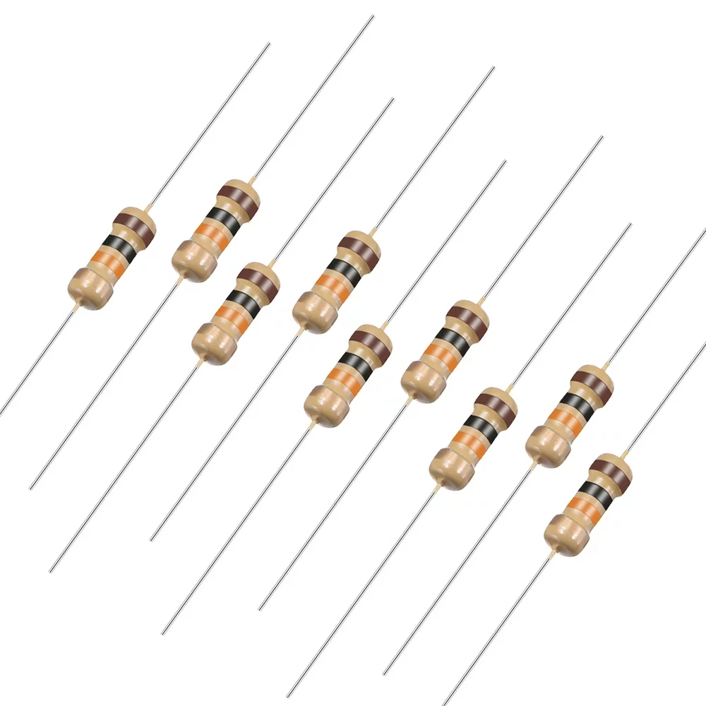
10 Ohm 0.25W Carbon Film Resistor (Pack of 50)
Carbon film resistors for setting hysteresis thresholds in op-amp Schmitt trigger circuits. Pack of 50 so you have plenty for experimentation.
Building a Schmitt Trigger with Op-Amp
While dedicated ICs like the 74HC14 are convenient, understanding how to build a Schmitt trigger from an op-amp gives you complete control over the threshold voltages and hysteresis width. This is essential when working with sensors that output voltages outside standard logic levels.
The op-amp Schmitt trigger uses positive feedback through a resistor divider. Here’s the inverting configuration:
Components:
- LM358 or LM741 op-amp (or any comparator like LM393)
- R1 = 10kΩ (feedback resistor, from output to non-inverting input)
- R2 = 10kΩ (from non-inverting input to midpoint reference)
- R3 = 100kΩ (input resistor, optional but recommended)
- VCC = 5V or 12V
Threshold calculation for a 5V single-supply inverting Schmitt trigger:
- VREF = VCC/2 = 2.5V (voltage at non-inverting input when output is at midpoint)
- VT+ = VREF × (1 + R1/R2) = 2.5 × (1 + 10k/10k) = 3.75V (when output is HIGH)
- VT- = VREF × R2/(R1+R2) = 2.5 × 10k/20k = 1.25V (when output is LOW)
- VH = VT+ – VT- = 2.5V
To adjust hysteresis: change R1. Larger R1 = wider hysteresis window (more noise immunity, slower response). Smaller R1 = narrower window (less immunity, faster response). The ratio R1/R2 is the key parameter.
For a window comparator (detects when signal is within a voltage range), connect two Schmitt triggers back-to-back with different threshold settings and feed both outputs into an AND gate.

10CM Female To Female Breadboard Jumper Wires 2.54MM – 40Pcs
Female-to-female jumper wires for connecting op-amp modules and IC breakout boards. Ideal for breadboard prototyping of Schmitt trigger circuits.
Practical Circuit Applications
The Schmitt trigger finds applications in nearly every area of electronics. Here are the most common practical uses that Indian hobbyists will find immediately useful:
1. Sensor Signal Conditioning
Photodiodes and LDRs produce slowly varying voltages as light levels change. Connecting them through a Schmitt trigger converts the gradual voltage change into a sharp, clean digital transition — no more flickering LEDs or chattering relay contacts when the light crosses the threshold.
2. Noise Filtering on Long Wire Runs
In industrial settings or large maker projects where signal wires run more than 50cm, Schmitt trigger inputs reject the capacitively-coupled noise from nearby power wires. This is why most sensor inputs on PLCs and microcontrollers are Schmitt trigger inputs.
3. Pulse Shaping
When a square wave travels through a long cable or is generated by a slow source like a Hall-effect sensor, the edges degrade into slow ramps. A Schmitt trigger restores the sharp edges needed for reliable clocking of digital circuits downstream.
4. Touch Sensor Interface
A simple touch sensor can be built with just a resistor and a Schmitt trigger input. The body capacitance (~10pF) and a large resistor (10MΩ) form an RC network whose time constant changes measurably when you touch it.
Button Debouncing with Schmitt Trigger
Mechanical push buttons bounce — when you press a button, the contacts physically bounce open and closed several times in the first 5–20ms before settling. This causes digital circuits to see multiple rapid transitions instead of a single clean press. A Schmitt trigger with an RC filter is the hardware solution:
Circuit: Connect a 10kΩ pull-up resistor from VCC to the button pin. Add a 100nF capacitor from the button pin to GND. Feed this RC node into a 74HC14 Schmitt trigger input.
How it works: When the button is pressed, the capacitor discharges slowly through the button’s contact resistance. The Schmitt trigger’s hysteresis ignores the bounce spikes because they don’t have enough time to fully cross VT+ before the capacitor pulls the voltage back. Only the genuine sustained press crosses both thresholds cleanly.
RC time constant calculation:
- τ = R × C = 10kΩ × 100nF = 1ms
- For 95% settling: 3τ = 3ms (safely longer than bounce duration)
- Maximum button press rate: limited to ~100 presses/second (fine for human interaction)
This hardware debounce circuit completely eliminates the need for software debounce delays, freeing up processing time on your microcontroller.
Schmitt Trigger Oscillator Circuit
One of the most useful applications of the 74HC14 is building a simple RC oscillator without any additional components. The Schmitt trigger’s hysteresis creates a self-oscillating relaxation oscillator:
Circuit: Connect a resistor R from the output back to the input. Add a capacitor C from the input to GND. That’s it — just one gate, one resistor, one capacitor.
Frequency formula:
f ≈ 1 / (1.2 × R × C)
Example calculations:
- R = 100kΩ, C = 100nF → f ≈ 83 Hz (audio/visual blink rate)
- R = 10kΩ, C = 10nF → f ≈ 8.3 kHz (audio range)
- R = 1kΩ, C = 100pF → f ≈ 833 kHz (RF/carrier range)
This oscillator is not as frequency-stable as a crystal oscillator, but it’s perfectly adequate for LED blinkers, tone generators, clock signals for slow digital circuits, and PWM generation. The frequency can be made adjustable by replacing R with a potentiometer.
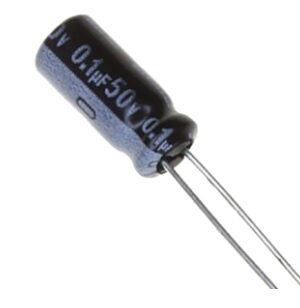
0.1µF 50V Capacitor (Pack of 50)
100nF / 0.1µF capacitors perfect for Schmitt trigger oscillator circuits and button debounce filters. Pack of 50 at an excellent value.
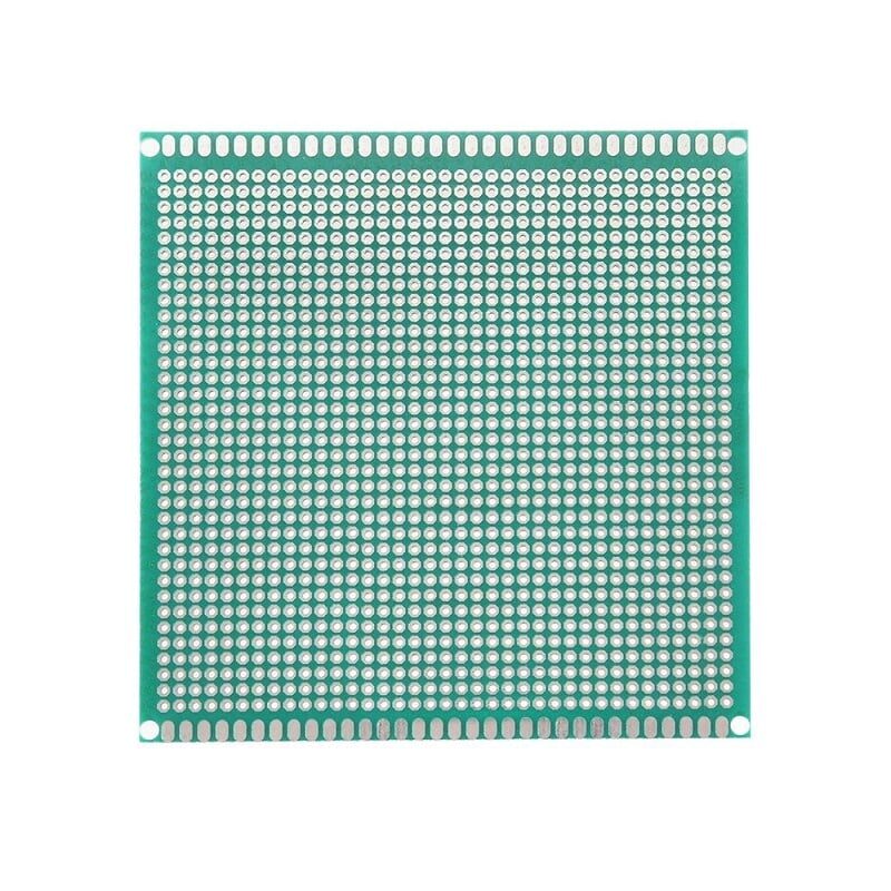
10 x 10 cm Universal PCB Prototype Board Single-Sided 2.54mm Hole Pitch
Universal perfboard for soldering your Schmitt trigger circuits permanently. 10x10cm single-sided PCB with standard 2.54mm pitch holes for DIP ICs.
Frequently Asked Questions
Q: What is the difference between a Schmitt trigger and a comparator?
A regular comparator has a single switching threshold — it switches whenever the input crosses that level, in either direction. This makes it sensitive to noise at the threshold. A Schmitt trigger adds hysteresis with two separate thresholds (VT+ and VT-), so it only switches when the input clearly moves past one threshold in one direction. Schmitt triggers are more robust for noisy real-world signals; comparators are better for precise threshold detection where hysteresis would introduce error.
Q: Can I use any logic gate as a Schmitt trigger?
No — only ICs specifically labelled as Schmitt trigger inputs have hysteresis. Regular CMOS logic gates (74HC00, 74HC04, etc.) do not have hysteresis and will oscillate or chatter when inputs are near the switching threshold. Look for the characteristic hysteresis symbol (a loop inside the gate symbol) on the datasheet. Common Schmitt trigger ICs include: 74HC14 (hex inverter), 74HC132 (quad NAND), 74HC7002 (quad NOR).
Q: How much hysteresis voltage do I need for my application?
For button debouncing: 1V of hysteresis is usually sufficient. For filtering supply noise: match hysteresis to the expected noise amplitude (measure with an oscilloscope). For slow sensor signals (temperature, light): wider hysteresis (1–2V) prevents chattering. For high-speed digital signals: minimise hysteresis (use fast comparators with ~50mV hysteresis) to avoid distorting timing.
Q: Why does my Schmitt trigger oscillator drift in frequency?
RC oscillators are inherently temperature-dependent because both resistors and capacitors change value with temperature. Typical drift is 0.1–1% per °C. For frequency-stable applications, use a crystal oscillator. For applications where rough frequency is acceptable (LED blinkers, buzzers, timers), the 74HC14 oscillator is perfectly adequate and costs almost nothing to build.
Q: Can I use a 74HC14 at 3.3V with an ESP32?
Yes, the 74HC family operates down to 2V. At 3.3V, the thresholds scale proportionally: VT+ ≈ 1.6V, VT- ≈ 0.8V, giving ~0.8V hysteresis. Input and output logic levels are compatible with 3.3V GPIO on ESP32, STM32, and Raspberry Pi. Just make sure VCC of the 74HC14 is 3.3V, not 5V, when interfacing with 3.3V logic.
Build cleaner circuits with the right components! Shop for logic ICs, resistors, capacitors, and breadboards at Zbotic Electronics Basics. Fast shipping across India — from Mumbai to Manipur, we’ve got your maker project covered!


Add comment