
Building a robotic dog with a 12-DOF quadruped design, servo actuators, and STM32 control is one of the most rewarding and technically demanding DIY robotics projects you can undertake. Unlike wheeled robots, a quadruped must solve inverse kinematics for every step, manage trot gaits in real time, and handle balance — all while staying within the power budget of hobby servos. This complete guide walks you through every stage: mechanical design, servo selection, STM32 firmware, inverse kinematics math, and gait implementation.
12-DOF Design Overview: Anatomy of a Quadruped
A 12-DOF (degrees of freedom) quadruped has four legs, each with 3 DOF — this is the minimum for full 3D leg workspace control. Each leg has three servo-driven joints:
- Hip abduction/adduction (HAA): Rotates the leg laterally, allowing the robot to step sideways and maintain balance during turns. Mounted at the shoulder.
- Hip flexion/extension (HFE): Swings the leg forward and backward — the primary propulsion joint.
- Knee flexion/extension (KFE): Controls leg reach and height. Combined with HFE, determines foot position in the sagittal plane.
Total: 4 legs × 3 joints = 12 servos. The naming convention follows biological leg joints: coxa (hip), femur (upper leg), tibia (lower leg). In hobby quadruped parlance, these are often called shoulder, upper arm, and forearm joints.
The key mechanical parameters to decide early:
- Body length and width: Typical small quadruped: 200mm × 120mm body. Leg span ~300mm.
- Leg link lengths: Coxa 40mm, femur 80mm, tibia 110mm is a common starting point. Longer tibias increase stride length; shorter tibias increase stability.
- Standing height: Target 120–180mm for a small hobby quadruped. Lower CoM = more stability.
- Foot contact: Rubber-tipped feet or 3D-printed hemispherical tips for traction.
Servo Selection: Torque, Speed, and Budget
Servo selection is the most critical hardware decision for a quadruped. Undersized servos will stall, overheat, and strip gears under load. Here is how to calculate the torque you need:
Torque Calculation
For the knee joint (KFE) carrying the most load: Assume robot mass M = 500g, 4 legs. In worst case (one leg supporting 50% of weight): Load at knee = 0.25kg × leg_length_from_knee = 0.25 × 0.11m = 0.027 N·m = 2.7 kg·cm. Add a 3× safety factor for dynamic loads: ~8 kg·cm required at the knee. Hip joints carry less load due to geometry but need higher speed for lateral motion.
Servo Classes for 12-DOF Quadruped
- Budget build (robot weight <500g): SG90 class (1.8 kg·cm). Marginal — works only if robot is ultralight (thin acrylic frame, no payload). Not recommended for reliable operation.
- Standard build (500g–1kg): MG90S or DS3218 (9–18 kg·cm). Good balance of size, torque, and cost. Metal gears essential. MG90S at 2.2 kg·cm is still light for knees — use DS3218 (15 kg·cm) at joints under heavy load.
- Serious build (1–2kg): 20–30 kg·cm digital servos. Dynamixel-class servos ($30–80 each) offer position feedback and daisy-chain communication — a significant advantage for 12-servo management.

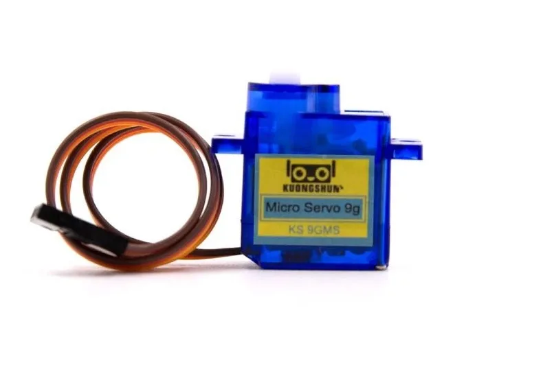
TowerPro SG90 180 Degree Rotation Servo Motor
Lightweight 9g servo suitable for low-load joints (coxa/shoulder) in small quadruped builds — 12 required for a full 12-DOF robot.

Servo Mount Holder Bracket for SG90/MG90 (Pack of 2)
Precision servo brackets essential for building repeatable quadruped leg joints — compatible with all SG90 and MG90 class servos.
Mechanical Build: Frame, Joints, and Assembly
The mechanical structure must be light, rigid, and repeatable. Three common frame materials:
- 3D printed PLA/PETG: Best for prototyping. Easy to iterate, low cost, but weaker than aluminum. Use 40% infill for structural parts. File repositories: GitHub has dozens of open-source quadruped designs (SpotMicro is the most popular open-source design).
- Laser-cut acrylic: Flat parts only, so body and mounting plates work well. Use 4mm acrylic for the body, 3mm for leg links. Bracket servos with custom standoffs.
- Aluminum extrusions and sheet: Heaviest but strongest. Appropriate for larger robots (1kg+) where servo torque is sufficient.
Assembly Sequence
- Build all four legs identically. Use a jig to ensure consistent link lengths.
- Mount servos in brackets. Secure with M2 screws — servo screw holes are M2 on SG90 class.
- Attach leg assemblies to body frame. Coxa servos mount parallel to body sides.
- Run servo signal wires through frame cavities to minimize cable snagging.
- Install electronics: STM32 board, PCA9685, BEC/power distribution, IMU.
- Balance check: place on flat surface with all joints at neutral. Body should sit level without servo correction.
STM32 Setup: Why STM32 Beats Arduino for Quadrupeds
The STM32 family of microcontrollers is the preferred platform for serious quadruped builds. Here is why it surpasses Arduino for this application:
- Hardware PWM channels: STM32F4 series has up to 16 hardware PWM channels. A 12-servo robot needs exactly 12 — Arduino Mega has only 15 software PWM, with timing jitter. STM32 hardware PWM runs at 50Hz with sub-microsecond precision.
- Clock speed: STM32F4 runs at 168 MHz vs Arduino Mega’s 16 MHz. The IK math (trigonometric calculations per step) executes in microseconds instead of milliseconds.
- FPU (Floating Point Unit): STM32F4 has a hardware FPU. Inverse kinematics requires
atan2(),sqrt(),cos()— the FPU makes these ~10× faster than software float on Arduino. - Multiple hardware timers: Run the servo update loop, IMU read loop, and gait state machine on independent timers with precise interrupt scheduling.
- UART/SPI/I2C abundance: Communicate simultaneously with IMU (I2C), Bluetooth module (UART), and debug terminal (UART) without bit-banging.
Recommended STM32 Boards
- STM32F4 Discovery: 168 MHz, hardware FPU, affordable. Good for learning STM32 HAL.
- STM32F103C8 (Blue Pill): Budget option, 72 MHz, no FPU. Adequate if using lookup tables instead of runtime trig.
- STM32G431: Modern, efficient, with built-in CORDIC math accelerator for trig functions.
For servo output management, use a PCA9685 16-channel PWM driver over I2C. This offloads PWM generation entirely, freeing STM32 timers for control loops. The STM32 sends 12 target positions to PCA9685 via I2C — PCA9685 generates the PWM signals independently.
Inverse Kinematics for Quadruped Legs
Inverse kinematics (IK) is the math that converts a desired foot position (x, y, z) into joint angles (coxa, femur, tibia). This is solved analytically for a 3-DOF leg, meaning no iterative solver is needed — the angles are computed directly from closed-form equations.
Step-by-Step IK for One Leg
Given desired foot position relative to hip joint (x_foot, y_foot, z_foot):
- Coxa angle:
θ_coxa = atan2(y_foot, x_foot)— projects foot onto the HAA plane. - Reach in the sagittal plane:
L = sqrt(x_foot² + y_foot²) - coxa_length - Effective reach to foot:
R = sqrt(L² + z_foot²) - Femur angle:
θ_femur = atan2(z_foot, L) + acos((femur² + R² - tibia²) / (2 × femur × R)) - Tibia angle:
θ_tibia = acos((femur² + tibia² - R²) / (2 × femur × tibia))
All angles are then mapped to servo PWM microsecond values. Define the neutral (0°) and range (±90°) for each servo at assembly time using calibration routines. Store these offsets in flash memory on the STM32.
Workspace Limits
Always clamp IK output: if R > (femur + tibia), the foot position is unreachable (singularity). Return an error and hold the last valid position. This prevents the servo from slamming to a limit stop, which strips gears in seconds.
Trot Gait Programming and Timing
The trot gait is the most efficient and natural gait for a quadruped. In a trot, diagonal pairs of legs move together: front-left + rear-right swing while front-right + rear-left support, then swap. This maintains two ground contacts at all times — providing reasonable stability while enabling good forward speed.
Gait Cycle Parameters
- Stride frequency: 1–3 Hz for a hobby quadruped. Start at 1 Hz (1 second per full gait cycle).
- Duty factor: Ratio of stance time to full cycle time. Trot typically uses 0.5 (50% stance, 50% swing).
- Step height: How high the foot lifts during swing phase. 20–40mm is typical. Higher = more terrain clearance, more servo work.
- Stride length: How far the foot moves forward during stance. 40–80mm for a small quadruped.
STM32 Implementation
Use a state machine with a hardware timer interrupt at 100Hz (10ms tick). The gait phase (0.0–1.0) increments each tick. For each leg, compute phase offset: front-left = 0.0, rear-right = 0.0, front-right = 0.5, rear-left = 0.5. For each leg at each tick: if in swing phase, compute foot trajectory (Bézier curve for smooth lift); if in stance phase, move foot backward linearly (body moves forward). Compute IK for each foot position, send 12 angles to PCA9685.
Servo SG90 9g 180 Degree (China Chip)
Cost-effective servo option for initial quadruped prototyping — buy 12 for a full 12-DOF robot build with plenty of spares.
Power Management and Battery Selection
Power is the quadruped builder’s nemesis. Twelve servos under load draw significant current:
- SG90 at stall: ~700mA each. Peak for all 12: ~8.4A. Operating average during trot: ~2–4A total.
- MG90S/DS3218 class: 1–2A at stall each. 12 at stall: 12–24A. Average: 4–8A.
Battery Recommendations
- LiPo 2S (7.4V) 2200mAh 30C: Best choice for SG90-class builds. Use a 5V 5A BEC to regulate for servos. Runtime: 20–40 minutes.
- LiPo 3S (11.1V) for higher-torque servos: Most 20+ kg·cm digital servos operate at 6–8.4V — use a high-current 6V or 7.4V BEC.
- Never power STM32 and servos from the same rail without a decoupling capacitor bank. Servo PWM spikes cause STM32 resets. Use 470µF–1000µF electrolytic capacitors across the servo power rail.
Add a main power switch and a separate logic power switch. Low battery voltage causes erratic servo behavior before complete shutdown — implement a voltage monitor on STM32 ADC to trigger a safe sit-down pose when battery drops below 6.8V (2S) or 10.0V (3S).
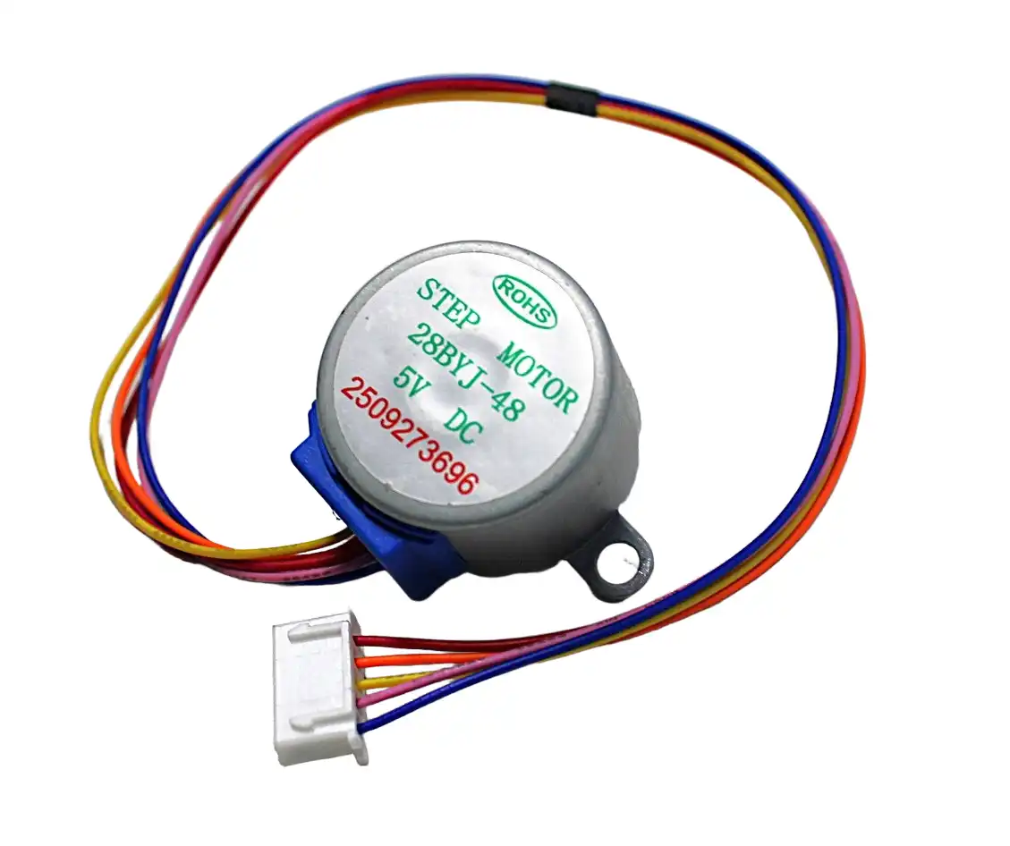
28BYJ-48 5V Stepper Motor
Useful for gantry mechanisms or camera pan/tilt on your robotic dog — low-cost stepper for precise angular positioning.
Frequently Asked Questions
How long does it take to build a 12-DOF quadruped?
A realistic timeline: mechanical assembly 8–15 hours, electronics wiring 3–5 hours, firmware setup and calibration 5–10 hours, IK and gait tuning 10–20 hours. Total: 25–50 hours spread over several weeks for most hobbyists. The SpotMicro open-source design has a community forum that significantly reduces debugging time.
Can I use Arduino instead of STM32?
Arduino Mega can control 12 servos via software PWM libraries like PCA9685 (offloads PWM generation). The 16MHz clock is the real bottleneck — IK math runs 10–20× slower than STM32F4. For slow gaits (1Hz) this is acceptable; for responsive dynamic gaits, STM32 is strongly preferred.
What is the SpotMicro design?
SpotMicro is a popular open-source 12-DOF quadruped design inspired by Boston Dynamics’ Spot. All STL files, BOM, and firmware are freely available on GitHub. It uses 12 DS3218 servos and runs on a Raspberry Pi. An excellent starting point for first-time quadruped builders.
How do I calibrate all 12 servos?
Write a calibration mode in firmware that sets each servo to 90° (1500µs). With the robot powered in calibration mode, mount each servo horn at the mechanical neutral position. This one-time calibration ensures that angle 0° in software equals straight (neutral) in hardware for each joint.
Do I need an IMU for a walking quadruped?
For basic trot gait on flat surfaces — no. Pre-programmed gaits work without IMU feedback. For terrain adaptation, slope compensation, or fall detection — yes. An MPU6050 connected to STM32 I2C provides roll/pitch data that can adjust gait parameters in real time.
Start your quadruped build today. Zbotic stocks everything from SG90 servos and servo brackets to ESP32 kits and motor controllers. Explore the full Robotics collection and get all 12 servos and brackets in one order.


Add comment