
Table of Contents
- What Is a PMIC Battery Charger?
- How Integrated Power Management ICs Work
- Key Features to Look For
- Popular PMIC and Charger ICs for Makers
- TP4056: The Maker’s Favourite Charger IC
- PCB Design Tips for Battery Charger Circuits
- Advanced PMICs for Multi-Rail Systems
- Frequently Asked Questions
If you have ever designed an embedded project that runs on a battery, you have faced the challenge of safely charging that battery while efficiently managing the power to your microcontroller, sensors, and peripherals. This is exactly what a PMIC battery charger — an integrated power management IC — is designed to solve. These chips combine battery charging control, protection circuits, voltage regulation, and power path management into a single compact package, dramatically simplifying hardware design. This guide explains how PMICs and battery charger ICs work, which ones to choose, and how to use them effectively in your projects.
What Is a PMIC Battery Charger?
A Power Management Integrated Circuit (PMIC) is a chip that integrates multiple power-related functions that were previously handled by separate ICs. In the context of battery-powered devices, a PMIC battery charger typically combines:
- Battery charger: Controls the charge current and voltage profile for safe lithium-ion or LiFePO4 charging (CC/CV — constant current / constant voltage)
- Battery protection: Overcharge, over-discharge, overcurrent, and short circuit protection
- Voltage regulator: One or more LDOs or DC-DC converters to power the system from the battery
- Power path management: Routes power from either the external supply or the battery depending on availability, often with seamless transition
- Fuel gauge: Estimates battery state-of-charge (SoC) using coulomb counting or voltage-based methods
- Load switch: Enables or disables power to subsystems for sleep mode current reduction
Not every chip includes all these features. Entry-level charger ICs like the TP4056 handle only the charging and protection functions. Full PMICs from companies like Texas Instruments (BQ series), Maxim, and Microchip integrate all of the above and communicate over I2C or SPI to a microcontroller.
For Indian hobbyists and electronics students, understanding PMIC architecture is increasingly important. Modern IoT devices, wearables, portable medical devices, and industrial sensors all rely on well-designed power management for battery life that meets user expectations.
How Integrated Power Management ICs Work
The core function of any Li-ion battery charger IC is implementing the CC/CV charging algorithm:
Phase 1: Pre-qualification (if battery is deeply discharged)
If the cell voltage is below ~3V, the charger applies a very small trickle current (10% of normal charge current) to bring the cell voltage up gently. Charging a deeply discharged lithium cell at full current can cause plating and dendrite growth, creating safety hazards.
Phase 2: Constant Current (CC)
Once the cell is above the pre-qualification threshold, the charger applies the programmed charge current (set by a resistor on most simple ICs) until the cell voltage reaches the regulation voltage (4.2V for standard Li-ion, 4.35V for high-voltage Li-ion, 3.6V for LiFePO4).
Phase 3: Constant Voltage (CV)
The charger holds the voltage at the regulation setpoint and allows the current to taper down naturally as the cell approaches full capacity. Charging is considered complete when the current drops to a termination threshold, typically 10% of the programmed charge current (e.g., 100mA termination for a 1A charge current).
Phase 4: Top-off and re-charge
Some chargers monitor the cell and initiate a top-off charge when voltage drops below a threshold (e.g., 4.05V), preventing the cell from sitting partially discharged for long periods.
The power path manager sits alongside this charging circuitry. When external power is present, it powers the system load from the external supply (not the battery) while simultaneously charging the battery. When external power is removed, the load transfers to the battery. This “instant-on” capability is important for applications that must not interrupt operation when plugging or unplugging.
Key Features to Look For
When selecting a PMIC or battery charger IC for your project, evaluate these parameters:
Input voltage range: Must accommodate your charging source — USB (4.5–5.5V), solar panel (variable), or adapter. Some PMICs accept up to 28V input, useful for solar applications.
Charge current range: Should match your battery capacity. A 1000mAh cell should charge at 500mA–1A (0.5C to 1C). The IC must support this range, ideally programmable via a resistor.
Battery chemistry support: Li-ion (4.2V), LiPo (4.2V), LiFePO4 (3.6V), NiMH — not all ICs support all chemistries. Verify the termination voltage.
Protection features: Look for overcharge voltage protection, over-discharge protection, overcurrent, short circuit, and thermal shutdown. Some chips also include cell temperature monitoring via NTC thermistor input.
Communication interface: Simple ICs have LED status outputs only. More capable PMICs offer I2C registers for reading charge status, fault codes, battery voltage, and current — valuable for logging and battery health monitoring.
Package and thermal performance: Higher charge currents require chips that can dissipate heat. Look at the thermal resistance (θJA) and ensure your PCB layout provides adequate copper area for heat spreading. SOT-23 packages for low-current applications, QFN for higher power.
Popular PMIC and Charger ICs for Makers
Here is a curated overview of ICs that Indian makers and students commonly use:
TP4056: The ubiquitous single-cell Li-ion charger. 1A charge current, USB input, LED charge/done indicators, thermal regulation. Available as bare IC and as ready-to-use modules. Excellent for beginner projects. Does not include a power path manager or fuel gauge.
MCP73831/MCP73832 (Microchip): Very small SOT-23-5 package, programmable charge current 15–500mA, suitable for small wearables and IoT sensors with small batteries. Widely used in Arduino-compatible boards.
BQ24210 / BQ24195L (Texas Instruments): More capable single/multi-cell chargers with I2C interface, power path management, USB current limiting, and system power. Used in commercial products.
IP5306 (INJOINIC): A near-complete power bank IC — integrates charger, boost converter, LED indicators, and load detection. Extremely popular in power bank modules. Available as modules at Zbotic.
BQ27441-G1 (Texas Instruments): A standalone fuel gauge IC (not a charger) that uses Impedance Track technology for accurate SoC estimation. Pairs with any charger IC for battery percentage readout over I2C.
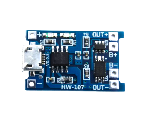
TP4056 1A Li-Ion Battery Charging Board – Micro USB with Current Protection
The classic TP4056 PMIC on a ready-to-use module with micro USB input and integrated DW01A protection. Ideal for single-cell Li-ion projects — plug in and start charging safely.
TP4056: The Maker’s Favourite Charger IC
The TP4056 deserves its own section because it is by far the most commonly used battery charger IC in the Indian maker community, and understanding it deeply prevents many common mistakes.
Key specifications:
- Input voltage: 4V to 8V (USB 5V is ideal)
- Charge current: Programmable via RPROG resistor (1.2kΩ → 1A, 2kΩ → 580mA, 10kΩ → 130mA)
- Termination voltage: 4.2V ± 1% (fixed)
- Termination current: 1/10 of programmed charge current
- Status outputs: CHRG (charging, active LOW) and STDBY (charge complete, active LOW)
- Thermal regulation: Reduces charge current if junction temperature exceeds 120°C
The protection module confusion: The bare TP4056 IC has NO over-discharge or overcurrent protection. It only controls charging. Ready-made modules that say “with protection” include a separate DW01A + FS8205A MOSFET pair that adds battery protection. Always use the protected module version for project builds — it protects both the battery and your circuit from catastrophic failure.
Power path limitation: The TP4056 does not include a power path manager. If you power your load from the OUT+ terminal of the protection IC while charging, the system works but the charge current available to the battery is the full programmed current minus what the load draws. Under heavy load during charging, the battery may not charge at all or may charge and discharge simultaneously (known as the “seesaw” problem). For reliable behaviour, either use a separate load switch or upgrade to an IC with integrated power path management like the IP5306.
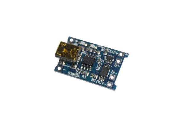
TP4056 1A Li-ion Lithium Battery Charging Module With Current Protection – Mini USB
Mini USB version of the TP4056 protected charging module. Compact form factor makes it easy to integrate into small project enclosures and wearable builds.
PCB Design Tips for Battery Charger Circuits
Designing a reliable battery charger circuit goes beyond just picking the right IC. Layout and component selection matter enormously:
1. Bypass capacitors: Place 10µF ceramic capacitors as close as possible to the VCC and BAT pins of your charger IC. Inductance in the PCB traces causes voltage spikes that can damage the IC or cause instability. Use X5R or X7R ceramic for stability across temperature.
2. Thermal relief: At 1A charge current, the TP4056 dissipates up to 500mW internally (at 5V input charging a near-empty battery). Add a solid copper fill (thermal pad) connected to the exposed pad if present, or use a ground plane under the IC to spread heat. Without this, the thermal regulation kicks in and reduces charge current, extending charge time.
3. RPROG resistor tolerance: Use 1% tolerance resistors for the RPROG pin to ensure accurate charge current setting. A 5% resistor can cause ±5% variation in charge current, which is acceptable but tighter tolerance is better for battery longevity.
4. Input reverse polarity protection: Add a Schottky diode (BAT54 or SS14) in series with the input to prevent damage from reverse polarity connection. Budget for the ~0.3V forward voltage drop in your input voltage minimum specification.
5. Battery connector polarity: Use a keyed connector (JST PH 2-pin is standard for LiPo packs) to prevent polarity reversal. Label polarity clearly on the PCB silkscreen.
Advanced PMICs for Multi-Rail Systems
For more complex projects — wearables with display, WiFi, and sensors; medical devices; industrial IoT nodes — a simple charger IC is insufficient. Full PMICs provide:
Multiple regulated outputs: A single PMIC generates 3.3V for the MCU, 1.8V for sensors, 1.2V for RF frontend, and 5V for USB peripherals — all from a single battery. This replaces four separate converter ICs with one chip.
Dynamic voltage scaling: Advanced PMICs can adjust core voltage in real time based on CPU performance requirements, a feature used in smartphones to extend battery life during idle periods. For embedded projects, this can reduce active current by 30–50%.
JEITA compliance: The Japan Electronics and Information Technology Industries Association (JEITA) defines charge current and voltage derating based on battery temperature. Quality PMICs with NTC thermistor input implement JEITA automatically, reducing charge current in hot or cold conditions to prevent damage.
USB Power Delivery support: Modern PMICs support USB-PD negotiation, accepting 9V, 12V, or 20V from USB-PD adapters and using the higher voltage to charge faster or to power higher-voltage systems directly.
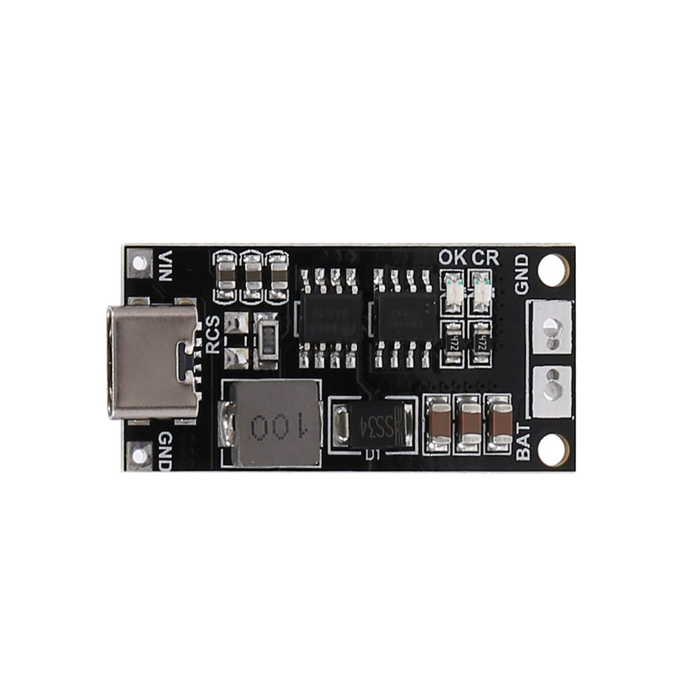
18650 Polymer Lithium Ion Charger Type C to 3S 12.6V 2A Booster Module
Multi-function module with Type-C charging input, 3S balancing BMS, and 12.6V boost output. A practical PMIC-like solution for 3-cell Li-ion packs powering 12V loads.
Frequently Asked Questions
What is the difference between a PMIC and a battery charger IC?
A battery charger IC handles only the charging function — controlling the CC/CV charge algorithm and protection. A PMIC (Power Management IC) is a superset that additionally includes voltage regulators, power path management, fuel gauge, and load switches. Some chips call themselves PMICs but only include charger + protection, which is technically a charger IC with protection. Read the datasheet to understand what functions are actually included.
Can I use a TP4056 to charge LiFePO4 batteries?
No. The TP4056 has a fixed termination voltage of 4.2V, which would overcharge LiFePO4 cells (maximum 3.6V). Overcharging LiFePO4 can cause permanent damage and is a safety hazard. Use a charger IC specifically designed for LiFePO4, or use a charger with adjustable termination voltage set correctly for your cell chemistry.
How do I read battery percentage in my Arduino project?
The simplest approach is to read battery voltage via an ADC pin (through a voltage divider if voltage exceeds the ADC reference). Map voltage to percentage using a lookup table specific to your battery chemistry. This is not very accurate because voltage vs. SoC is highly non-linear for Li-ion. For better accuracy, use a dedicated fuel gauge IC like the MAX17043 over I2C — it has an Arduino library and provides percentage directly.
Is it safe to charge a LiPo battery with the TP4056 while it is connected to my Arduino?
Yes, but understand the limitation: the TP4056 does not have power path management. The battery powers the Arduino, and the TP4056 tries to charge the battery at the same time. If the Arduino draws more than the charge current, the battery discharges even while plugged in. Also ensure the total current (charge + load) does not exceed your USB adapter’s rating. For robust designs, use an IC with power path management instead.
What happens if I connect a higher-capacity battery to a TP4056 module?
The TP4056 charges at its programmed rate (typically 1A on standard modules) regardless of battery capacity. A larger battery simply takes longer to charge — there is no damage from using a higher capacity cell. However, the TP4056 is not suitable for parallel cell configurations because it cannot balance cells. For multi-cell packs, use a proper BMS with per-cell balancing.
Start Your PMIC Battery Charger Project Today
Understanding PMIC battery charger ICs opens the door to building truly professional battery-powered electronics. Start with the accessible TP4056 module for simple single-cell projects, then graduate to multi-function modules and full PMICs as your designs grow in complexity. All the charging modules, BMS boards, and battery holders you need for your power management projects are available at Zbotic.in — your one-stop electronics shop in India with fast delivery nationwide.


Add comment