
If you’ve ever tried to control more than a couple of servos directly from a Raspberry Pi, you’ve run into an immediate problem: the Pi’s GPIO pins don’t generate hardware PWM signals on enough channels to drive a multi-servo robot reliably. The solution used by robotics engineers worldwide is the PCA9685 servo shield Raspberry Pi 16 servos combination — a 16-channel I2C PWM driver that offloads all the timing-critical PWM generation to dedicated hardware, leaving your Pi’s CPU free for higher-level logic. This tutorial covers everything from wiring to Python code to real project applications.
Why PCA9685 for Raspberry Pi Servo Control?
The Raspberry Pi generates software PWM on any GPIO pin using the RPi.GPIO library, but software PWM has two fundamental problems for servo control. First, the Linux kernel is not a real-time OS — other system processes can interrupt PWM generation, causing timing glitches that make servos jitter unpredictably. Second, software PWM is CPU-intensive; running 8 channels of software PWM at 50 Hz eats a meaningful chunk of CPU time that could go toward camera processing, pathfinding, or web serving.
The PCA9685 solves both problems. It contains a dedicated internal oscillator (25 MHz) that generates hardware-accurate PWM signals entirely independently of the Pi’s CPU. The Pi communicates with it only to set channel values — a brief I2C transaction — and the PCA9685 maintains those PWM outputs autonomously. The result: 16 jitter-free servo channels at the cost of just two GPIO pins (SDA + SCL) and about 2 µs of CPU time per update.
PCA9685 Hardware Overview
The PCA9685 is an I2C-controlled 12-bit PWM controller from NXP Semiconductors. Key specifications:
- Channels: 16 independent PWM outputs
- PWM resolution: 12-bit (4096 steps per cycle)
- PWM frequency: 24 Hz to 1526 Hz (configurable — set to 50 Hz for standard servos)
- I2C address: 0x40 (default), configurable via A0–A5 address pins to any of 64 addresses
- Logic voltage: 2.3V to 5.5V (3.3V compatible — works directly with Pi’s GPIO)
- Output current: 10 mA per channel (signal only — servo power must come from external supply)
The board breaks out 16 3-pin servo headers (GND / V+ / Signal). The V+ rail on these headers connects to the VCC jumper which you bridge from either the board’s 5V logic rail or an external servo power supply. This is the most important hardware detail covered next.
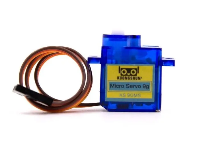
Servo SG90 9g 180 Degree
The classic SG90 micro servo — perfect for starting a 16-servo PCA9685 project with an affordable, widely-supported servo.
Wiring to Raspberry Pi
The PCA9685 requires just four connections to the Raspberry Pi:
| PCA9685 Pin | Raspberry Pi Pin | Notes |
|---|---|---|
| VCC | Pin 1 (3.3V) | Logic power only |
| GND | Pin 6 (GND) | Common ground |
| SDA | Pin 3 (GPIO2/SDA1) | I2C data |
| SCL | Pin 5 (GPIO3/SCL1) | I2C clock |
Enable I2C on the Pi if you haven’t already: sudo raspi-config → Interface Options → I2C → Enable. Verify the PCA9685 is detected: sudo i2cdetect -y 1 — you should see 0x40 in the output grid.
Servo Power Supply Considerations
This is the most commonly misunderstood part of the PCA9685 setup and the source of most unexplained servo behaviour. Never power servos from the Raspberry Pi’s 5V pin. The Pi’s 5V rail (powered from the USB input) is typically rated at 2–2.5A total, and a single SG90 servo can draw 500 mA under load. Six servos can easily draw 3A — far exceeding what the Pi can supply, causing brownouts and SD card corruption.
The correct approach: use a separate 5V power supply rated for at least 500 mA × (number of servos) with a 20–30% headroom. For 16 SG90 servos: plan for 8A at 5V — use a 10A 5V supply. Connect this supply’s positive terminal to the PCA9685’s V+ terminal, and connect its GND to the shared GND that also connects to the Pi’s GND. This shared GND is mandatory for the PWM signal reference to work correctly.

TowerPro SG90 180 Degree Rotation Servo Motor
Original TowerPro SG90 servo — reliable and consistent, ideal for building a full 16-servo robot arm or hexapod leg assembly.
Python Setup & Libraries
The easiest way to control the PCA9685 from Python is with Adafruit’s CircuitPython libraries. Install them:
pip3 install adafruit-circuitpython-pca9685
pip3 install adafruit-circuitpython-servokit
The ServoKit class is the highest-level interface and handles all the PWM-to-angle conversion for you. For lower-level control (useful for ESCs and LEDs), use the PCA9685 class directly.
Control Code: Single & Multi-Servo Examples
Basic: Move one servo to a specific angle
from adafruit_servokit import ServoKit
import time

# 16-channel PCA9685
kit = ServoKit(channels=16)

# Move servo on channel 0 to 90 degrees
kit.servo[0].angle = 90
time.sleep(1)

# Sweep servo 0 from 0 to 180
for angle in range(0, 181, 5):
    kit.servo[0].angle = angle
    time.sleep(0.02)
Advanced: Control all 16 servos in a wave pattern
import math, time
from adafruit_servokit import ServoKit

kit = ServoKit(channels=16)

# Wave pattern across all 16 servos
for t in range(200):
    for ch in range(16):
        phase = (ch / 16.0) * 2 * math.pi
        angle = 90 + 70 * math.sin(2 * math.pi * t / 50 + phase)
        kit.servo[ch].angle = angle
    time.sleep(0.02)
To set custom pulse widths (useful when your servo’s actual range doesn’t match the 544–2400 µs default):
kit.servo[0].set_pulse_width_range(500, 2500)  # microseconds
kit.servo[0].angle = 0    # 500µs = 0°
kit.servo[0].angle = 180  # 2500µs = 180°
Chaining Multiple PCA9685 Boards
Each PCA9685 has six address bits (A0–A5) configurable by soldering bridge pads. This allows up to 62 boards (addresses 0x40–0x7D, with 0x70 reserved for broadcast) on a single I2C bus — that’s 992 servo channels from two Pi GPIO pins. In practice, I2C capacitance limits you to about 8–10 boards on a standard I2C bus without a repeater.
To use two boards:
import board, busio
from adafruit_pca9685 import PCA9685
from adafruit_servokit import ServoKit

kit1 = ServoKit(channels=16, address=0x40)  # Default
kit2 = ServoKit(channels=16, address=0x41)  # A0 bridge soldered

kit1.servo[0].angle = 45
kit2.servo[0].angle = 135
Project Ideas: Hexapod, Robot Arm, Pan-Tilt
Hexapod robot (18 servos): A 6-legged robot with 3 DOF per leg needs 18 servos. One PCA9685 handles 16, a second handles the remaining 2 (or 6 if you want to extend to 3 legs × 6 DOF). The Raspberry Pi runs the inverse kinematics and gait generation, sending position commands over I2C at 50 Hz while the PCA9685 maintains precise PWM output without CPU load.
5-DOF Robot arm (5 servos): Perfect single PCA9685 project. Use channels 0–4 for base, shoulder, elbow, wrist pitch, and wrist roll. Channel 5 can drive the gripper. Remaining channels 6–15 are available for sensor-feedback servos or a camera pan-tilt.
Pan-tilt camera (2 servos): A simple 2-servo pan-tilt is the classic PCA9685 introductory project. Track a face or coloured object using OpenCV on the Pi, converting bounding box coordinates to pan/tilt servo angles and updating the PCA9685 via I2C in real time.

Servo Mount Holder Bracket For SG90/MG90 (Pack of 2)
Sturdy servo mounting brackets for SG90 and MG90 servos — essential hardware for building multi-servo robot arms and hexapod legs.
Frequently Asked Questions
Can I use PCA9685 with Arduino instead of Raspberry Pi?
Absolutely. The PCA9685 works with any I2C-capable microcontroller. On Arduino, use the Adafruit PWM Servo Driver library (Adafruit_PWMServoDriver). The wiring is identical — connect SDA to A4, SCL to A5 on an Arduino Uno, or use the dedicated I2C pins on the Mega. The code is nearly identical to the Arduino Servo library in simplicity.
What is the maximum PWM frequency of the PCA9685?
The PCA9685 can be configured from 24 Hz to approximately 1526 Hz. For standard hobby servos, use 50 Hz (20 ms period). For digital servos that accept 330 Hz, you can significantly increase position update rate. For ESC control, 50–400 Hz is typical. Do not run standard analog servos above 100 Hz as it stresses the motor electronics.
Why do my servos jitter with PCA9685?
Jitter with PCA9685 is almost always a power supply issue. The servo power rail droops when multiple servos move simultaneously, causing position errors. Solution: add a 470 µF–1000 µF capacitor across the servo power rail (V+ to GND on the PCA9685 board). This bulk capacitor absorbs inrush current spikes. Also check that your GND is properly shared between the PCA9685 and Pi.
How many servos can one PCA9685 power?
The PCA9685 IC itself only provides PWM signals — it does not source servo power. The number of servos is limited by your external power supply, not the PCA9685. The board has 16 PWM output channels, so 16 servos maximum per board. With chained boards at different I2C addresses, you can control 992 channels from a single Raspberry Pi.
Does PCA9685 work with MG996R high-torque servos?
Yes. The PCA9685 only needs to drive a 3.3V PWM signal wire — the heavy current for MG996R (up to 2.5A stall) comes from your external servo power supply, not from the PCA9685. Make sure your supply can handle the combined stall current of all servos that might move simultaneously, typically 1–2A per MG996R under load.
Conclusion
The PCA9685 servo shield Raspberry Pi 16 servos combination is the gold standard for multi-servo control in maker and robotics projects. By offloading all PWM generation to the PCA9685’s dedicated hardware, you free the Raspberry Pi to focus on the high-level logic that makes your robot intelligent — computer vision, path planning, network communication — without sacrificing servo precision or introducing CPU-induced jitter.
Whether you’re building a graceful hexapod, a precise robot arm, or an expressive animatronic face, the PCA9685 gives you reliable control of up to 16 servos from just two GPIO pins. Find SG90 servos, MG90 brackets, and robot chassis for your next project at Zbotic’s Robotics & DIY store.


Add comment