
NRF24L01 Two-Way Communication: Full Duplex Example Arduino
If you want to add wireless communication to your Arduino projects, the nrf24l01 two way communication Arduino setup is one of the most reliable and cost-effective solutions available. The NRF24L01 is a 2.4 GHz transceiver module capable of both transmitting and receiving data simultaneously, making it ideal for remote sensors, RC cars, home automation, and drone telemetry systems. In this guide, we will walk you through a complete full duplex (bidirectional) example using two Arduino boards and two NRF24L01 modules.
What is the NRF24L01 Module?
The NRF24L01 is a single-chip 2.4 GHz transceiver module manufactured by Nordic Semiconductor. It operates in the 2.400–2.525 GHz ISM band and supports data rates of 250 kbps, 1 Mbps, and 2 Mbps. Unlike simple RF transmitter/receiver pairs, the NRF24L01 can both send and receive data, making it perfect for building bidirectional wireless links.
Key features that make it popular among Indian hobbyists and makers:
- Very affordable — typically available under ₹150 per module
- Ultra-low power consumption (900 nA in power-down mode)
- Up to 125 configurable channels
- Range up to 100 metres with the basic module, 1 km+ with the PA+LNA variant
- SPI interface — works with virtually every microcontroller
- Supports up to 6 data pipes simultaneously
- Built-in Enhanced ShockBurst™ protocol for automatic ACK and retransmission
The standard NRF24L01 module has a small PCB antenna, while the NRF24L01+PA+LNA version adds a power amplifier and low-noise amplifier with an external antenna for longer-range applications.
Components Needed
To build the NRF24L01 two-way communication setup, you will need the following components:
- 2x NRF24L01 2.4 GHz transceiver modules
- 2x Arduino Uno, Nano, or Mega boards
- Jumper wires and breadboards
- 100 µF capacitor (optional but highly recommended — placed across VCC and GND of the NRF24L01 to stabilize power)
- USB cables for programming
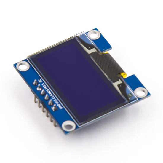
- OLED display (optional, for displaying received data)

0.96 Inch I2C OLED LCD Module (SSD1306)
Display received NRF24L01 data in real time. This 4-pin I2C OLED module is easy to integrate with Arduino and provides a crisp, high-contrast white display.
Wiring the NRF24L01 to Arduino
The NRF24L01 uses the SPI (Serial Peripheral Interface) protocol. The pinout is as follows:
| NRF24L01 Pin | Arduino Uno Pin | Description |
|---|---|---|
| VCC | 3.3V | Power supply (3.3V ONLY — do NOT use 5V) |
| GND | GND | Ground |
| CE | D9 | Chip Enable |
| CSN | D10 | Chip Select Not |
| SCK | D13 | SPI Clock |
| MOSI | D11 | Master Out Slave In |
| MISO | D12 | Master In Slave Out |
| IRQ | Not connected | Interrupt (optional) |
Important: The NRF24L01 runs on 3.3V logic and power. Never connect VCC to the Arduino’s 5V pin — it will damage the module. The Arduino Uno’s SPI pins are 5V tolerant when used as inputs to the NRF24L01, but the VCC must strictly be 3.3V. Adding a 10–100 µF electrolytic capacitor across VCC and GND of the NRF24L01 dramatically improves stability.
Installing the RF24 Library
The most widely used Arduino library for NRF24L01 is the RF24 library by TMRh20. Install it through the Arduino IDE Library Manager:
- Open Arduino IDE → Sketch → Include Library → Manage Libraries
- Search for
RF24by TMRh20 - Click Install
Alternatively, you can download it from GitHub (TMRh20/RF24). The library supports Arduino Uno, Mega, Nano, ESP8266, ESP32, and Raspberry Pi.
Full Duplex Two-Way Communication Code
For genuine two-way (full duplex) communication with NRF24L01, we use the concept of pipes. Node 1 writes on pipe address 0xF0F0F0F0E1LL and reads on pipe 0xF0F0F0F0D2LL. Node 2 is configured in reverse. Both nodes alternate between transmit and receive modes.
Node 1 (Transmitter / Receiver A) Code:
#include <SPI.h>
#include <RF24.h>

RF24 radio(9, 10); // CE, CSN

// Pipe addresses
const uint64_t pipeA = 0xF0F0F0F0E1LL; // Node 1 writes here
const uint64_t pipeB = 0xF0F0F0F0D2LL; // Node 1 reads here

struct DataPacket {
  float temperature;
  float humidity;
  int nodeID;
};

void setup() {
  Serial.begin(9600);
  radio.begin();
  radio.setPALevel(RF24_PA_LOW);
  radio.setDataRate(RF24_250KBPS);
  radio.setChannel(108);
  radio.openWritingPipe(pipeA);
  radio.openReadingPipe(1, pipeB);
  radio.startListening();
  Serial.println("Node 1 Ready");
}

void loop() {
  // Send data
  radio.stopListening();
  DataPacket myData = {25.4, 60.2, 1};
  bool success = radio.write(&myData, sizeof(myData));
  if (success) Serial.println("Sent OK");
  else Serial.println("Transmit failed");

  delay(10);

  // Receive response
  radio.startListening();
  unsigned long startTime = millis();
  while (!radio.available() && millis() - startTime < 200);

  if (radio.available()) {
    DataPacket received;
    radio.read(&received, sizeof(received));
    Serial.print("Received from Node ");
    Serial.print(received.nodeID);
    Serial.print(": Temp=");
    Serial.print(received.temperature);
    Serial.print(" Humidity=");
    Serial.println(received.humidity);
  }
  delay(1000);
}
Node 2 (Transmitter / Receiver B) Code:
#include <SPI.h>
#include <RF24.h>

RF24 radio(9, 10); // CE, CSN

const uint64_t pipeA = 0xF0F0F0F0E1LL; // Node 2 reads here
const uint64_t pipeB = 0xF0F0F0F0D2LL; // Node 2 writes here

struct DataPacket {
  float temperature;
  float humidity;
  int nodeID;
};

void setup() {
  Serial.begin(9600);
  radio.begin();
  radio.setPALevel(RF24_PA_LOW);
  radio.setDataRate(RF24_250KBPS);
  radio.setChannel(108);
  radio.openWritingPipe(pipeB);
  radio.openReadingPipe(1, pipeA);
  radio.startListening();
  Serial.println("Node 2 Ready");
}

void loop() {
  if (radio.available()) {
    DataPacket received;
    radio.read(&received, sizeof(received));
    Serial.print("Got from Node 1: Temp=");
    Serial.println(received.temperature);

    // Send reply
    radio.stopListening();
    DataPacket reply = {32.1, 45.8, 2};
    radio.write(&reply, sizeof(reply));
    radio.startListening();
  }
}
Upload Node 1 code to the first Arduino and Node 2 code to the second. Open Serial Monitor (9600 baud) on both and you should see bidirectional data exchange.

Ai Thinker ESP32 CAM Development Board WiFi+Bluetooth
Upgrade your wireless project with the ESP32 CAM — combine NRF24L01 data relay with live video streaming over WiFi for advanced IoT builds.
Troubleshooting Common Issues
The NRF24L01 is notoriously sensitive to power supply noise. Here are the most common problems and solutions:
1. Module not detected / write always fails
Add a 100 µF capacitor across VCC and GND. The Arduino 3.3V pin can sometimes supply insufficient current, especially if other peripherals share it. Try powering the NRF24L01 from a dedicated 3.3V LDO regulator.
2. Intermittent communication / data corruption
Lower the data rate to RF24_250KBPS for longer range and better noise immunity. Use a channel above 100 to avoid interference from Wi-Fi (which uses 2.4 GHz channels 1–11, corresponding to NRF24L01 channels 0–83).
3. Only one-way communication works
Make sure the pipe addresses on both nodes are swapped correctly. Node 1’s writing pipe must match Node 2’s reading pipe, and vice versa.
4. Range is too short
Switch from RF24_PA_LOW to RF24_PA_HIGH or RF24_PA_MAX. For outdoor or through-wall use, upgrade to the NRF24L01+PA+LNA module with an external antenna.
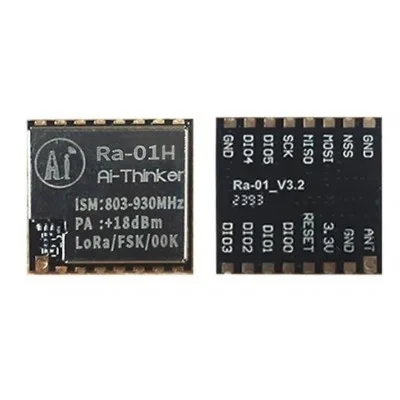
Ai Thinker LoRa Ra-01H Module
Need range beyond 100m? Upgrade to LoRa for kilometre-scale wireless links. Perfect for farm monitoring, smart city, and outdoor sensor networks.
Real-World Project Ideas
Once you have the NRF24L01 two-way communication working on Arduino, here are some practical projects to build:
- Wireless RC Car Controller: Send joystick values from a handheld transmitter to a car and receive battery/speed telemetry back.
- Home Automation: Multiple sensor nodes report temperature, humidity, and PIR motion data to a central Arduino hub which drives relays for lights and fans.
- Wireless Glove Controller: Use flex sensors in a glove to send hand gesture data to a robot arm remotely.
- Mesh Sensor Network: Using the RF24Network library, build a mesh where each node can relay messages — ideal for large farms or multi-floor buildings.
- Wireless Scoreboard: Two sporting venues exchange score updates over NRF24L01 for a live scoreboard display.

1 Channel 12V 30A Relay Module with Optocoupler
Control high-power loads wirelessly using NRF24L01 + Arduino + this robust 30A relay module with optocoupler isolation. Ideal for home automation builds.
0.96 Inch SPI OLED LCD Module (Blue SSD1306)
Display wireless sensor readings directly on this compact blue OLED. Compact and power-efficient, great for battery-powered NRF24L01 nodes.
Frequently Asked Questions
Can NRF24L01 send and receive data at the same time (true full duplex)?
Strictly speaking, the NRF24L01 is a half-duplex device — it can transmit or receive at any given moment, but not both simultaneously. However, its Enhanced ShockBurst protocol switches between TX and RX so quickly (within microseconds) that it feels like full duplex in practical applications. By time-sharing the channel rapidly, you achieve effective bidirectional communication.
How many NRF24L01 modules can communicate with each other?
A single NRF24L01 can communicate with up to 6 nodes simultaneously using its 6 data pipes. For larger networks with dozens or hundreds of nodes, use the RF24Network or RF24Mesh libraries which implement star and mesh topologies on top of the basic RF24 library.
What is the maximum range of NRF24L01?
The standard NRF24L01 module achieves 50–100 metres in open space. The PA+LNA variant with an external antenna can reach 500–1000 metres or more in line-of-sight conditions. Walls, interference from other 2.4 GHz devices (Wi-Fi, Bluetooth), and metal structures reduce effective range.
Why does my NRF24L01 only work when held close but fail at distance?
This is almost always a power supply issue. Use a dedicated 3.3V regulator instead of the Arduino’s onboard 3.3V pin, which is rated for only 50 mA. Add a 100 µF capacitor between VCC and GND on the NRF24L01, and try setting PA level to MAX.
Does NRF24L01 work with ESP32 or ESP8266?
Yes. The RF24 library supports ESP32 and ESP8266. On ESP8266, use pins D1/D2 for CE/CSN. On ESP32, use GPIO4/GPIO5 or any available GPIO. Both platforms operate at 3.3V which matches the NRF24L01’s requirements perfectly, eliminating voltage mismatch issues.
Ready to Build Your Wireless Project?
Get all the components you need for your NRF24L01 Arduino two-way communication project from Zbotic — India’s trusted electronics component store with fast shipping across Mumbai, Delhi, Bangalore, and all major cities. Explore our full range of wireless communication modules and build something amazing today!


Add comment