
Understanding the ESP32 NodeMCU pinout GPIO PWM ADC reference is the first and most important step before building any ESP32 project. Unlike simple Arduino boards where almost every pin can be used interchangeably, the ESP32 has specific pins reserved for boot strapping, internal use, and peripheral functions. Using the wrong pin can cause your ESP32 to fail to boot, behave erratically, or produce incorrect readings. This comprehensive pinout guide covers every aspect of ESP32 GPIO functionality — from basic digital I/O to ADC channels, PWM, I2C, SPI, and UART — everything you need as a reference for your IoT projects.
ESP32 Hardware Overview
The ESP32 is a dual-core Xtensa LX6 32-bit microcontroller from Espressif Systems, running at up to 240MHz. It integrates WiFi (802.11 b/g/n), Bluetooth Classic, and BLE into a single chip, making it one of the most capable and cost-effective microcontrollers available to Indian makers today.
Key hardware specs relevant to pinout:
- Total GPIO pins: 34 physical GPIO pins on the ESP32 chip (GPIO0–GPIO39)
- Output-capable pins: GPIO0–GPIO33 (GPIO34–GPIO39 are input-only)
- ADC channels: 18 channels across two ADC units (ADC1: 8 channels, ADC2: 10 channels)
- DAC outputs: 2 channels (GPIO25 and GPIO26)
- Touch sensors: 10 capacitive touch pins
- PWM channels: 16 channels via LEDC peripheral (any output-capable GPIO)
- I2C: 2 hardware I2C controllers (any GPIO)
- SPI: 4 SPI controllers (2 for internal flash, VSPI and HSPI available)
- UART: 3 UART interfaces
The NodeMCU-32S is the most common ESP32 development board form factor in India. It exposes 36 GPIO pins on two rows of 19 pins each, with a CP2102 or CH340 USB-to-Serial chip for programming. The pinout discussion in this guide applies to the standard 38-pin ESP32-WROOM-32 module used in most NodeMCU-32S boards.
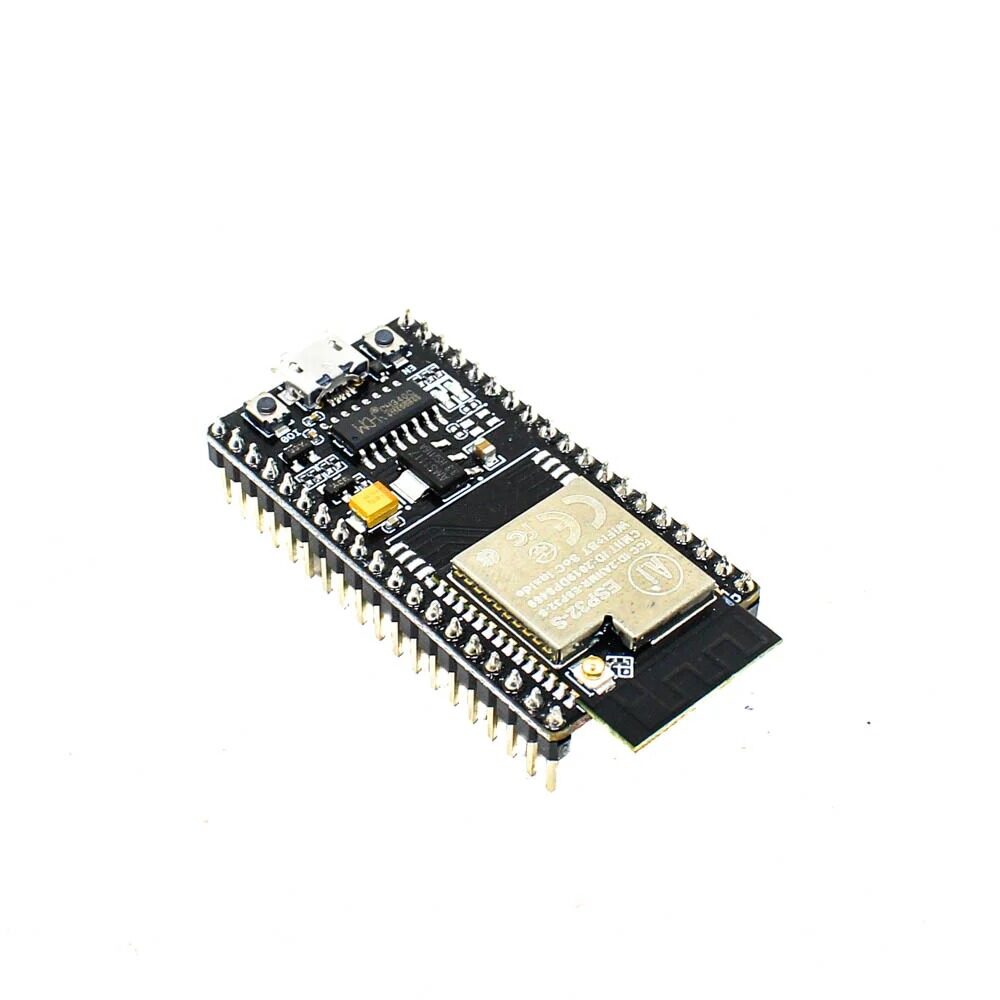
Ai Thinker NodeMCU-32S ESP32 Development Board – IPEX Version
The NodeMCU-32S is the reference board for this pinout guide. It exposes 36 GPIO pins with clear silk-screen labeling, includes an IPEX antenna connector for external antenna, and has a built-in CP2102 USB-to-serial converter.
GPIO Pin Reference Table
This table covers all accessible GPIO pins on the NodeMCU-32S (ESP32-WROOM-32) board, with their key functions and limitations:
| GPIO | Input | Output | Notes |
|---|---|---|---|
| GPIO0 | Pulled Up | OK | Boot fail if LOW. Boot button on most boards. Avoid for input. |
| GPIO1 | TX pin | OK | UART0 TX. Debug output during boot. Avoid for project I/O. |
| GPIO2 | OK | OK | Onboard LED on many boards. Must be LOW or float at boot. |
| GPIO3 | RX pin | OK | UART0 RX. Avoid for project I/O. |
| GPIO4 | OK | OK | General purpose. Touch0. Reliable, recommended for most uses. |
| GPIO5 | OK | OK | VSPI CS. Outputs PWM at boot. Pull-up during boot. |
| GPIO6-11 | NO | NO | Connected to internal SPI flash. DO NOT USE. |
| GPIO12 | OK | OK | Boot fail if pulled HIGH. JTAG TDI. HSPI MISO. Use with care. |
| GPIO13 | OK | OK | JTAG TCK. HSPI MOSI. Safe to use. |
| GPIO14 | OK | OK | JTAG TMS. HSPI CLK. Outputs PWM at boot. |
| GPIO15 | OK | OK | JTAG TDO. HSPI CS. Must be HIGH at boot. Outputs PWM at boot. |
| GPIO16 | OK | OK | UART2 RX. Often used for PSRAM on some modules. |
| GPIO17 | OK | OK | UART2 TX. Safe general-purpose GPIO. |
| GPIO18 | OK | OK | VSPI CLK. Recommended for SPI clock. |
| GPIO19 | OK | OK | VSPI MISO. Recommended for SPI MISO. |
| GPIO21 | OK | OK | Default I2C SDA. Highly recommended for I2C projects. |
| GPIO22 | OK | OK | Default I2C SCL. Highly recommended for I2C projects. |
| GPIO23 | OK | OK | VSPI MOSI. Recommended for SPI MOSI. |
| GPIO25 | OK | OK | DAC1 output. ADC2 channel 8. General purpose safe. |
| GPIO26 | OK | OK | DAC2 output. ADC2 channel 9. General purpose safe. |
| GPIO27 | OK | OK | Touch7. ADC2 channel 7. General purpose safe. |
| GPIO32 | OK | OK | ADC1 channel 4. Touch9. Reliable for ADC use. |
| GPIO33 | OK | OK | ADC1 channel 5. Touch8. Reliable for ADC use. |
| GPIO34 | OK | INPUT ONLY | ADC1 channel 6. No internal pull-up/down. Input only. |
| GPIO35 | OK | INPUT ONLY | ADC1 channel 7. No internal pull-up/down. Input only. |
| GPIO36 (VP) | OK | INPUT ONLY | ADC1 channel 0. No pull-up/down. Input only. |
| GPIO39 (VN) | OK | INPUT ONLY | ADC1 channel 3. No pull-up/down. Input only. |
ADC (Analog-to-Digital Converter) Pins
The ESP32 has two ADC units with a total of 18 channels, providing 12-bit resolution (0–4095 values for 0–3.3V). This is significantly more analog capability than the Arduino Uno’s single 10-bit ADC.
ADC1 (GPIO32–GPIO36, GPIO39) — SAFE to use with WiFi:
- GPIO32 → ADC1_CH4
- GPIO33 → ADC1_CH5
- GPIO34 → ADC1_CH6 (input only)
- GPIO35 → ADC1_CH7 (input only)
- GPIO36 (VP) → ADC1_CH0 (input only)
- GPIO39 (VN) → ADC1_CH3 (input only)
ADC2 (GPIO0, GPIO2, GPIO4, GPIO12–GPIO15, GPIO25–GPIO27) — CONFLICTS with WiFi:
This is the most important ESP32 ADC gotcha: ADC2 is used by the WiFi driver. When WiFi is active, you CANNOT use ADC2 channels. Attempting to read ADC2 while WiFi is active returns an error. Always use ADC1 channels for analog readings in WiFi-connected projects.
// Reading ADC on ESP32
int rawValue = analogRead(34);  // ADC1_CH6, input-only pin
float voltage = rawValue * (3.3 / 4095.0);
Serial.println(voltage);

// ADC attenuation for different voltage ranges
// Default: 0-1.1V (no attenuation)
analogSetAttenuation(ADC_11db);  // 0-3.3V full range (most common)
// Or per-pin:
analogSetPinAttenuation(34, ADC_11db);
ADC Accuracy Note: The ESP32’s ADC is known to be non-linear, especially at the extremes (near 0V and near 3.3V). For high-accuracy measurements, use an external ADC like the ADS1115 via I2C. For general sensor readings (temperature, light level, potentiometer), the built-in ADC is adequate.

LM35 Temperature Sensors
The LM35 is a classic analog temperature sensor perfect for testing ESP32 ADC. Connect its output to GPIO32 (ADC1_CH4) for accurate temperature readings even while WiFi is active. Output is 10mV/°C.
PWM: LED Control on Any GPIO
The ESP32 has a dedicated LEDC (LED Control) peripheral with 16 independent channels, each capable of generating PWM signals. Any output-capable GPIO can be assigned to any LEDC channel. This is much more flexible than Arduino Uno, which has only 6 fixed PWM pins.
// ESP32 LEDC PWM - works on any output GPIO
const int ledPin = 21;     // GPIO21
const int pwmChannel = 0;  // LEDC channel 0 (0-15)
const int pwmFreq = 5000;  // 5 kHz frequency
const int pwmResolution = 8; // 8-bit resolution (0-255)

void setup() {
  // Configure LEDC channel
  ledcSetup(pwmChannel, pwmFreq, pwmResolution);
  // Attach GPIO to LEDC channel
  ledcAttachPin(ledPin, pwmChannel);
}

void loop() {
  // Fade LED in
  for (int dc = 0; dc = 0; dc--) {
    ledcWrite(pwmChannel, dc);
    delay(10);
  }
}
PWM for Servo Motors: Use LEDC with 50Hz frequency and 16-bit resolution for servo control. Map servo angles (0-180°) to pulse widths of 1ms-2ms (1000-2000 microseconds) within the 20ms period:
ledcSetup(0, 50, 16);  // 50Hz, 16-bit
ledcAttachPin(servoPin, 0);

// Angle to duty cycle conversion for 50Hz/16-bit
int angle = 90; // degrees
int duty = map(angle, 0, 180, 1638, 8192); // 1ms to 2ms in 16-bit
ledcWrite(0, duty);
I2C Pins: Default and Custom Assignments
The ESP32 has two I2C controllers (I2C0 and I2C1) and — unlike most microcontrollers — allows you to assign any GPIO pins as SDA/SCL. The Arduino Wire library defaults to:
- Default SDA: GPIO21
- Default SCL: GPIO22
These defaults work with Wire.begin() and no additional arguments. For custom pins or to use the second I2C controller:
#include <Wire.h>

// Default I2C (GPIO21=SDA, GPIO22=SCL)
Wire.begin();

// Custom I2C pins
Wire.begin(SDA_PIN, SCL_PIN);
// Example: Wire.begin(16, 17);

// Second I2C bus on ESP32
TwoWire I2C_two = TwoWire(1); // Use I2C controller 1
I2C_two.begin(13, 14, 400000); // SDA=13, SCL=14, 400kHz
The ability to use custom I2C pins is invaluable when the default pins are occupied (e.g., by a display using SPI on GPIO21 for its reset line). Common I2C sensors and their typical addresses: BME280 (0x76/0x77), BMP280 (0x76/0x77), SSD1306 OLED (0x3C/0x3D), MPU6050 (0x68/0x69).
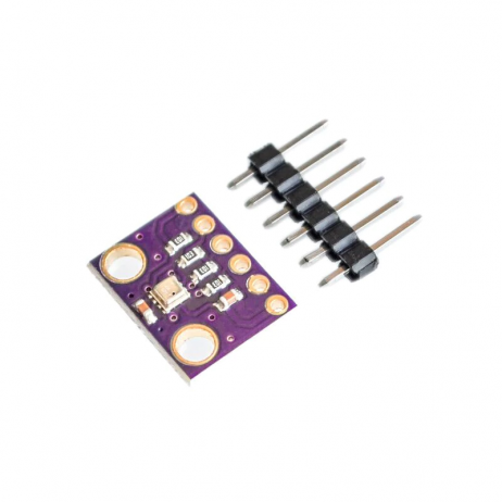
GY-BME280-3.3 Precision Altimeter Atmospheric Pressure Sensor Module
A classic I2C sensor to test with ESP32’s default I2C pins (GPIO21=SDA, GPIO22=SCL). Provides temperature, humidity, and barometric pressure over I2C at address 0x76 or 0x77 depending on the SDO pin state.
SPI Pins: VSPI and HSPI
The ESP32 has four SPI controllers: SPI0 and SPI1 are used internally for the flash memory and cache (do not touch these). VSPI (SPI2) and HSPI (SPI3) are available for external peripherals.
| Signal | VSPI (SPI2) Default | HSPI (SPI3) Default |
|---|---|---|
| MOSI | GPIO23 | GPIO13 |
| MISO | GPIO19 | GPIO12 |
| SCK | GPIO18 | GPIO14 |
| CS | GPIO5 | GPIO15 |
Like I2C, the SPI pins are also configurable. You can run multiple SPI devices on the same bus using different CS pins, or use custom pins entirely. Use VSPI (GPIO18/19/23) as your primary SPI bus for most projects — these pins have no boot-time restrictions.
Avoid GPIO12 (HSPI MISO) as a CS or MOSI line — if pulled HIGH at boot, the ESP32 changes the flash voltage and will fail to boot. Keep GPIO12 low during power-on.
UART Serial Communication Pins
The ESP32 has three hardware UART interfaces, all configurable to any GPIO:
- UART0: GPIO1 (TX), GPIO3 (RX) — Used by USB-Serial (Arduino Serial). Avoid for project use.
- UART1: GPIO10 (TX), GPIO9 (RX) — Default pins are on the internal flash! Remap to safe pins.
- UART2: GPIO17 (TX), GPIO16 (RX) — Safe to use for external serial devices.
#include <HardwareSerial.h>

// UART2 on default pins
HardwareSerial SerialPort(2);

void setup() {
  Serial.begin(115200);     // UART0 via USB
  SerialPort.begin(9600);   // UART2 at GPIO16/17
}

// Custom UART1 pins (remap away from internal flash)
HardwareSerial GPS_Serial(1);
GPS_Serial.begin(9600, SERIAL_8N1, 25, 26); // RX=GPIO25, TX=GPIO26
Special-Purpose and Input-Only Pins
Boot Strapping Pins
These pins are sampled during boot to determine the boot mode. Incorrect states prevent normal operation:
- GPIO0: Must be HIGH for normal boot. LOW = download/flash mode. This is the BOOT button on most boards.
- GPIO2: Must be LOW or floating during flashing. HIGH = uploads are blocked.
- GPIO5: Must be HIGH during boot (internal pull-up).
- GPIO12: Must be LOW at boot (sets flash voltage). Pulling HIGH = flash voltage changes = boot failure.
- GPIO15: Must be HIGH at boot (prevents debug log output on UART0).
Input-Only Pins (GPIO34, GPIO35, GPIO36, GPIO39)
These four pins are connected to the ESP32’s ADC and RTC circuitry but have no output drivers. Key limitations:
- Cannot be set as OUTPUT — will generate an error or be silently ignored
- No internal pull-up or pull-down resistors — must provide external pull resistors
- Excellent for ADC readings and low-noise analog inputs
- GPIO36 (labeled VP) and GPIO39 (labeled VN) on most NodeMCU boards

30Pin ESP32 Expansion Board with Type-C USB and Micro USB Dual Interface
This expansion board makes working with ESP32 GPIO much easier — it breaks out all 30 pins with labeled headers and supports both Type-C and Micro USB. Perfect for prototyping with multiple sensors and peripherals simultaneously.
Frequently Asked Questions
Which ESP32 GPIO pins are completely safe to use without any restrictions?
The safest general-purpose GPIO pins for both input and output are: GPIO4, GPIO13, GPIO16, GPIO17, GPIO18, GPIO19, GPIO21, GPIO22, GPIO23, GPIO25, GPIO26, GPIO27, GPIO32, GPIO33. These have no boot-time restrictions, no conflicts with internal peripherals, and support both input and output with pull-up/down resistors. For input-only use, GPIO34, GPIO35, GPIO36, and GPIO39 are also excellent for analog inputs.
Why does analogRead() give wrong values when WiFi is on?
This happens when you are trying to read an ADC2 pin while WiFi is active. ADC2 is shared with the WiFi driver. Switch to ADC1 pins (GPIO32, GPIO33, GPIO34, GPIO35, GPIO36, GPIO39) for analog readings in WiFi projects. ADC1 is entirely independent and unaffected by WiFi activity.
Can ESP32 GPIO pins handle 5V logic levels?
No. The ESP32 is a 3.3V device and its GPIO pins are NOT 5V tolerant. Applying 5V to a GPIO pin will damage the chip over time and can cause immediate failure. Use a voltage divider or a level shifter when interfacing with 5V devices like Arduino or older sensors. For outputs driving 5V peripherals, a MOSFET or level shifter is required.
How many PWM channels can run simultaneously on ESP32?
The ESP32 LEDC peripheral supports 16 independent PWM channels running simultaneously. Channels 0-7 use a high-speed timer and channels 8-15 use a low-speed timer. All 16 can run at different frequencies and duty cycles at the same time, allowing you to independently control 16 LEDs, servos, or other PWM devices simultaneously.
What is the difference between NodeMCU-32S, ESP32 DevKit v1, and ESP32-WROOM-32?
The ESP32-WROOM-32 is the core module (the metal-shielded component with the antenna). The DevKit v1 and NodeMCU-32S are development boards built around this module. Both have the same ESP32 chip and pinout. The main differences are the USB-to-serial chip (DevKit v1 uses CP2102, some NodeMCU variants use CH340), pin labeling, and physical dimensions. For this pinout guide, all three are functionally identical in terms of GPIO assignments.
Get Your ESP32 Modules and Accessories from Zbotic
Now that you have a complete ESP32 pinout reference, it is time to build! Shop for ESP32 development boards, sensors, expansion boards, and all the components you need at Zbotic. Fast shipping across India, genuine components from trusted brands like Ai Thinker and Waveshare.


Add comment