
If you have ever tried to debug an I2C, SPI, or UART communication problem with just a multimeter or even an oscilloscope, you know how frustrating it can be. A logic analyzer for Arduino, STM32, and other microcontrollers transforms that debugging process from guesswork into clarity — capturing digital signals, decoding protocols, and showing you exactly what your firmware is transmitting and receiving. This guide covers the best budget logic analyser options available in India today.
What Is a Logic Analyser and Why Do You Need One?
A logic analyser is a measurement instrument that captures the state of multiple digital signals simultaneously over time and displays them as timing diagrams. Unlike an oscilloscope that shows signal amplitude (voltage), a logic analyser is only concerned with whether a signal is HIGH or LOW at any given moment.
This makes logic analysers uniquely powerful for debugging digital communication protocols. When your Arduino is sending I2C commands to a sensor and the sensor is not responding, the logic analyser will show you every clock pulse and data bit — often revealing a wrong address, a missing ACK, or an incorrect baud rate within seconds.
For anyone doing serious embedded development with Arduino Uno, Arduino Mega, Arduino Nano, STM32 Blue Pill, STM32 Nucleo, ESP8266, or ESP32, a logic analyser is arguably more useful day-to-day than an oscilloscope.
How Logic Analysers Work
A logic analyser samples each input channel at a fixed rate — for example, 24 MSa/s — and records a 1 or 0 depending on whether the input voltage exceeds the logic threshold (typically 1.6–2.0 V for 3.3 V logic, or 2.5 V for 5 V logic). The captured data stream is then interpreted by software that knows the timing rules for specific protocols.
For a 400 kHz I2C bus, a 24 MSa/s logic analyser captures 60 samples per I2C clock cycle — more than enough resolution to decode addresses, data bytes, ACK/NAK bits, and error conditions reliably. For 4 Mbps SPI, you need at least 8–10 MSa/s per channel, and for 10+ Mbps interfaces, higher-end analysers are required.
Types: USB vs Standalone vs Mixed-Signal
USB Logic Analysers (like the popular 8-channel clone) connect to a PC and rely on software for display and decoding. They are compact, very affordable, and well-supported by open-source tools. Ideal for beginners and hobbyists.
Standalone Logic Analysers have their own display and controls. More expensive, but do not require a PC. Examples include the Saleae Logic Pro (premium) or DSLogic Plus (mid-range).
Mixed-Signal Oscilloscopes (MSO) combine analogue channels (oscilloscope) with digital channels (logic analyser) in one instrument. Premium option — scopes like the Rigol MSO5000 series. Useful when you need to correlate analogue and digital signals on the same timeline.
For most Indian hobbyists and students, a USB logic analyser with sigrok support is the right starting point — outstanding value and capability for the money.
Top Budget Logic Analysers for India
1. Saleae Logic 8 Clone (8-Channel, 24 MHz) — Best Entry Option
The most popular logic analyser in the hobbyist market is the 8-channel, 24 MHz USB device often sold as a “Saleae Logic clone” or simply “USB Logic Analyser 8-Channel.” This device is based on the Cypress FX2 chip (same as the Hantek 6022BE) and is fully supported by sigrok with the fx2lafw driver.
It can sample at up to 24 MSa/s per channel and supports all major protocols via PulseView’s decoder library. Price in India: typically ₹400–₹800. This is an extraordinary value proposition.
Limitations: The cheap clone hardware can have reliability issues at very high sample rates. Cables are short. Input protection is minimal — be careful not to connect 5V+ signals to devices that do not handle them.
2. Kingst LA1010 (10-Channel, 100 MHz) — Best Mid-Range
The Kingst LA1010 steps up significantly: 10 channels, 100 MHz maximum sample rate, and a well-regarded proprietary desktop application (KingstVIS) that includes a clean protocol decoder. It requires proprietary firmware so is not sigrok-compatible, but the KingstVIS software is actually quite good. Price: ₹2,500–₹4,000.
3. DSLogic Plus (16-Channel, 400 MHz) — Advanced Users
The DreamSourceLab DSLogic Plus offers 16 channels, 400 MHz sample rate, and hardware-accelerated triggering. It runs DSView (open-source) software and is also sigrok-compatible. At ₹8,000–₹15,000, it bridges the gap to professional instruments and is suited for serious embedded development work.
4. Salaea Logic Pro 8 / Logic Pro 16 — Professional
The genuine Saleae Logic Pro series (not clones) offers the industry-leading Logic 2 software, which has the most polished protocol decoder experience available. These are priced at US$399–US$799 and are primarily used in professional embedded development environments. Zbotic does not stock these, but they are worth mentioning for completeness.
sigrok and PulseView: The Free Protocol Decoder
sigrok is a free, open-source signal analysis framework that supports over 100 logic analyser and oscilloscope devices. PulseView is its graphical front-end and is the recommended tool for using USB logic analysers on Linux, Windows, and macOS.
Protocol decoders available in PulseView include:
- I2C, I2S, SPI, UART, RS-232, RS-485, CAN bus, LIN bus
- 1-Wire, Dallas DS18B20 temperature sensor protocol
- JTAG, SWD (Serial Wire Debug for ARM Cortex)
- USB 1.x full-speed, PS/2 keyboard/mouse
- DHT11/DHT22, HC-SR04 ultrasonic, NEC IR remote
- Dozens more — the full list is at sigrok.org/wiki/Protocol_decoders
For Arduino and STM32 work, having I2C, SPI, UART, and SWD decoders available for free is enormously powerful. Stack decoders are supported — for example, decode raw I2C, then stack an MPU-6050 IMU decoder on top to see register reads in plain text.
Common Protocols You Can Decode
Understanding which protocols you need to debug helps you choose the right logic analyser:
I2C: Used by most sensors (BME280, MPU-6050, OLED displays, RTC modules). Standard speeds: 100 kHz (standard), 400 kHz (fast), 1 MHz (fast-plus). Any 24 MSa/s analyser handles these trivially.
SPI: Used by SD cards, TFT displays, flash memory, high-speed ADCs/DACs. Speeds from 1 MHz to 50+ MHz. For SPI above 4 MHz, use at least a 100 MHz sample-rate analyser.
UART: Serial console, GPS modules, HC-05 Bluetooth, SIM800 GSM. Baud rates from 300 to 115200 bps in hobby use, up to 3 Mbps in professional use. Any 24 MSa/s analyser handles standard baud rates easily.
1-Wire: DS18B20 temperature sensors, iButton devices. Very slow protocol — any logic analyser works.
JTAG / SWD: Programming and debugging ARM Cortex-M cores (STM32, nRF52, etc.). Requires JTAG-aware software; sigrok supports both.
Setting Up With Arduino and STM32
Getting started with a USB logic analyser and your microcontroller is straightforward:
- Install PulseView from sigrok.org/wiki/Downloads for your OS. On Windows, also install the Zadig USB driver tool to switch the device to WinUSB.
- Connect channels: Attach logic analyser channels (typically colour-coded wires) to the signal pins on your Arduino or STM32. Always connect the GND wire to circuit ground.
- Voltage levels: Most USB logic analysers accept 3.3 V and 5 V logic. For 3.3 V STM32 boards, verify the analyser input threshold — 3.3 V logic may not reliably trigger a 5 V-threshold input.
- Add a protocol decoder in PulseView by clicking the yellow-and-green icon. Select I2C, SPI, or UART as appropriate and assign channels.
- Run a capture and observe decoded data in the annotation layer above the raw digital waveform.
A common pitfall: always ensure the logic analyser GND is connected to the circuit GND. Floating ground references cause erratic readings that are impossible to decode.
Recommended Accessories for Logic Analyser Work

Female to Female Jumper Wires 40Pcs
Connect logic analyser clips to Arduino or STM32 pin headers quickly and reliably — these are essential for any debugging session.

Male to Female Jumper Wires 40Pcs
Ideal for tapping signals from breadboard rows to logic analyser input clips without disturbing your prototype circuit.
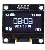
1.3″ I2C OLED Display Module
A perfect I2C device to practice protocol decoding — use your logic analyser to capture the initialisation sequence and display commands from Arduino.
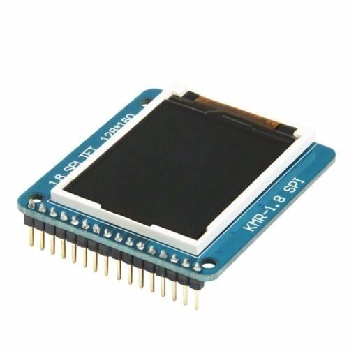
1.8″ SPI TFT LCD Display Module for Arduino
A great SPI device to decode — capture the SPI clock, MOSI, and chip-select lines to understand how your Arduino drives the display driver IC.
Frequently Asked Questions
What is the difference between a logic analyser and an oscilloscope?
An oscilloscope measures analogue voltage over time — showing waveform shape, amplitude, frequency, and noise. A logic analyser only captures HIGH/LOW states on many channels simultaneously and is optimised for protocol decoding. For embedded debugging, you often need both; but if you can only afford one, a logic analyser is more immediately useful for I2C/SPI/UART debugging.
Can I use a logic analyser with a 3.3V STM32?
Yes, but verify the input threshold of your logic analyser. Most cheap USB analysers accept 3.3 V and 5 V logic correctly. The high threshold must be below 3.3 V (typically 1.6 V) for 3.3 V signals to register as logic HIGH reliably.
How many channels do I need for Arduino I2C debugging?
I2C uses 2 lines (SDA and SCL) plus ground — so 3 connections total. An 8-channel analyser gives you plenty of headroom. For SPI, you need 4 channels (MISO, MOSI, SCK, CS). An 8-channel device covers all common protocols with channels to spare.
Is the Saleae clone as good as the genuine Saleae Logic?
For basic protocol decoding at standard speeds, the 8-channel clone with sigrok/PulseView is excellent. The genuine Saleae Logic 2 software offers a far better user experience, better high-speed performance, and professional support — worth the premium for professional development. For students and hobbyists, the clone is hard to beat at its price.
Can a logic analyser decode CAN bus?
Yes. sigrok’s PulseView includes a CAN bus decoder. For CAN at standard bit rates (250 kbps, 500 kbps, 1 Mbps), a 24 MSa/s analyser is sufficient. You will need a CAN transceiver (like the SN65HVD230) to interface between the differential CAN bus and the single-ended logic analyser input.
Level up your debugging toolkit. Zbotic has the components, modules, and accessories you need to build a professional electronics workbench. Explore Tools & Equipment →


Add comment