
The L293D motor driver IC is one of the most taught, most used, and most misunderstood components in the beginner electronics world. Every Arduino motor shield, every robotics kit, and virtually every introductory course on motor control features this little 16-pin DIP chip. And for good reason — it lets any microcontroller drive motors that draw far more current than the microcontroller’s GPIO pins can safely supply.
In this complete guide, we explain the H-bridge theory behind the L293D, walk through every pin of the IC, show you how to wire it for two DC motors and for a stepper motor, provide working Arduino code, and point out the most common wiring mistakes that destroy the chip.
1. What Is the L293D?
The L293D is a quadruple half-H driver IC manufactured by STMicroelectronics and Texas Instruments. In plain language: it contains four independent transistor half-bridge circuits, which can be combined in pairs to form two full H-bridges — allowing bidirectional control of two DC motors, or combined for one stepper motor.
Key specifications:
- Supply voltage (logic, VSS): 4.5 V – 36 V
- Supply voltage (motor, VS): 4.5 V – 36 V
- Output current per channel: 600 mA continuous, 1.2 A peak
- Total package dissipation: 4 W (DIP-16, no heatsink)
- Built-in flyback diodes: Yes (the "D" in L293D)
- Logic input levels: TTL and CMOS compatible
The "D" suffix is critical. The L293 (without D) has no internal flyback diodes and requires external diodes to protect against inductive voltage spikes from motor coils. Always use the L293D for motor driving.
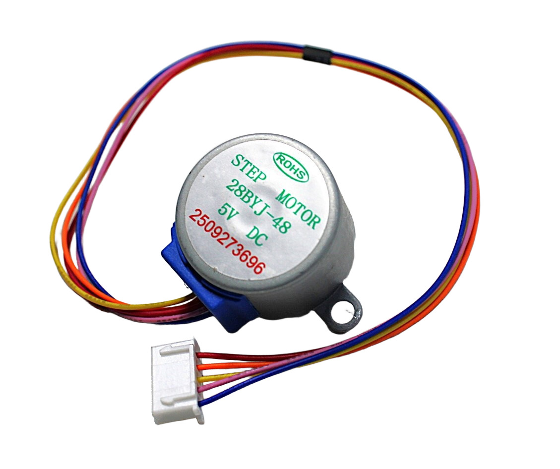
28BYJ-48 5V Stepper Motor
The classic starter stepper motor — pairs perfectly with the L293D for learning stepper control with Arduino. Low cost, widely available.
2. H-Bridge Theory Explained
To spin a DC motor in both directions, you need to reverse the voltage across its terminals. An H-bridge circuit does exactly this using four switches (transistors in practice) arranged in an H shape.
Imagine the motor in the middle of the letter H, and each of the four corners is a switch:
- Forward: Close top-left and bottom-right switches → current flows left to right through motor
- Reverse: Close top-right and bottom-left switches → current flows right to left through motor
- Brake: Close both bottom switches → motor terminals shorted, motor brakes
- Coast: All switches open → motor free-spins
The one thing you must NEVER do is close both switches on the same side (top-left + bottom-left) simultaneously. This shorts VCC to GND directly — a shoot-through fault that destroys the IC instantly. The L293D’s internal logic prevents this when input pins are driven correctly.
Speed control is achieved by PWM on the Enable pin. The L293D can switch at up to 5 kHz, making it compatible with any standard Arduino PWM frequency.
3. L293D Pinout – All 16 Pins
The L293D comes in a 16-pin DIP or SO package. The pinout is symmetrical — the left half controls Motor 1, the right half controls Motor 2.
| Pin | Name | Description |
|---|---|---|
| 1 | Enable 1,2 | Enable pin for channels 1 & 2 (Motor 1). HIGH = enabled. Connect to PWM for speed control. |
| 2 | Input 1 | Direction control for Output 1. Connect to Arduino digital pin. |
| 3 | Output 1 | Motor terminal A (Motor 1 +) |
| 4, 5 | GND | Ground. Also acts as heat sink — connect both to GND and a copper pour or heatsink. |
| 6 | Output 2 | Motor terminal B (Motor 1 –) |
| 7 | Input 2 | Direction control for Output 2 |
| 8 | VSS | Motor power supply (4.5–36 V). This powers the motor side. |
| 9 | Enable 3,4 | Enable pin for channels 3 & 4 (Motor 2). Same as pin 1 but for Motor 2. |
| 10 | Input 3 | Direction control for Output 3 |
| 11 | Output 3 | Motor terminal A (Motor 2 +) |
| 12, 13 | GND | Ground (heat sink side 2) |
| 14 | Output 4 | Motor terminal B (Motor 2 –) |
| 15 | Input 4 | Direction control for Output 4 |
| 16 | VCC | Logic supply voltage (4.5–36V). Powers the internal logic. Connect to 5V from Arduino. |
Important: VCC (pin 16) is the logic supply for the IC’s internal gates. VSS (pin 8) is the power supply that goes to the motor. These can be different voltages — logic at 5 V, motor at 12 V, for example.
4. Wiring Two DC Motors
Here is the standard wiring for controlling two DC motors with an Arduino Uno and L293D:
- Pin 16 (VCC) → Arduino 5V
- Pin 8 (VSS) → External motor power supply (e.g., 9V battery or 12V adapter) positive
- Pins 4, 5, 12, 13 (GND) → Common ground (Arduino + power supply ground)
- Pin 1 (EN1,2) → Arduino digital pin 5 (PWM for Motor 1 speed)
- Pin 2 (IN1) → Arduino digital pin 4
- Pin 7 (IN2) → Arduino digital pin 3
- Pins 3, 6 (OUT1, OUT2) → Motor 1 terminals
- Pin 9 (EN3,4) → Arduino digital pin 10 (PWM for Motor 2 speed)
- Pin 10 (IN3) → Arduino digital pin 9
- Pin 15 (IN4) → Arduino digital pin 8
- Pins 11, 14 (OUT3, OUT4) → Motor 2 terminals
Logic truth table for motor control:
| EN | IN1 | IN2 | Motor Action |
|---|---|---|---|
| HIGH | HIGH | LOW | Forward |
| HIGH | LOW | HIGH | Reverse |
| HIGH | HIGH | HIGH | Brake |
| LOW | X | X | Motor off (coast) |
5. Driving a Stepper Motor
The L293D can drive a unipolar stepper motor like the 28BYJ-48 by using all four output channels. Connect the motor’s four coil wires to OUT1, OUT2, OUT3, OUT4 and tie the motor’s common wire(s) to the motor supply voltage (VSS, pin 8).
For the 28BYJ-48 specifically:
- Red wire → VSS (5V motor supply)
- Orange wire → OUT1 (pin 3)
- Yellow wire → OUT2 (pin 6)
- Pink wire → OUT3 (pin 11)
- Blue wire → OUT4 (pin 14)
For full-step mode, energise the coils in sequence: 1010 → 0110 → 0101 → 1001 → 1010 (repeat).
For half-step mode (smoother, more positions): 1000 → 1010 → 0010 → 0110 → 0100 → 0101 → 0001 → 1001 → repeat.
6. Arduino Code Examples
Two DC Motors — Forward and Reverse
// L293D Motor Driver — Two DC Motors
// Motor 1: EN=5, IN1=4, IN2=3 | Motor 2: EN=10, IN3=9, IN4=8

#define EN1 5
#define IN1 4
#define IN2 3
#define EN2 10
#define IN3 9
#define IN4 8

void setup() {
  pinMode(EN1, OUTPUT); pinMode(IN1, OUTPUT); pinMode(IN2, OUTPUT);
  pinMode(EN2, OUTPUT); pinMode(IN3, OUTPUT); pinMode(IN4, OUTPUT);
}

void motorForward(int en, int in1, int in2, int spd) {
  analogWrite(en, spd);  // 0-255 for speed
  digitalWrite(in1, HIGH);
  digitalWrite(in2, LOW);
}

void motorReverse(int en, int in1, int in2, int spd) {
  analogWrite(en, spd);
  digitalWrite(in1, LOW);
  digitalWrite(in2, HIGH);
}

void motorStop(int en) {
  analogWrite(en, 0);
}

void loop() {
  motorForward(EN1, IN1, IN2, 200);   // Motor 1 forward, 78% speed
  motorForward(EN2, IN3, IN4, 200);   // Motor 2 forward
  delay(2000);
  motorReverse(EN1, IN1, IN2, 150);   // Motor 1 reverse, 59% speed
  motorReverse(EN2, IN3, IN4, 150);
  delay(2000);
  motorStop(EN1); motorStop(EN2);
  delay(1000);
}
28BYJ-48 Stepper Motor
#include <Stepper.h>
// 28BYJ-48: 2048 steps per revolution (in half-step mode)
const int stepsPerRevolution = 2048;
Stepper myStepper(stepsPerRevolution, 4, 6, 5, 7);

void setup() {
  myStepper.setSpeed(10); // RPM
}
void loop() {
  myStepper.step(2048);  // One full clockwise revolution
  delay(500);
  myStepper.step(-2048); // One full anticlockwise revolution
  delay(500);
}
7. L293D vs L298N
The L298N is the big brother of the L293D. Here is how they compare:
| Feature | L293D | L298N |
|---|---|---|
| Max current per channel | 600 mA / 1.2A peak | 2A / 3A peak |
| Flyback diodes | Built-in (D suffix) | External (on module) |
| Voltage drop | ~1.4 V per side | ~2 V per side |
| Package | DIP-16 (IC only) | Module (with heatsink) |
| Best for | Small motors, steppers up to 600 mA | Larger DC motors, 2A stepper motors |
For the 28BYJ-48 stepper and small DC gear motors, the L293D is ideal. For NEMA 17 stepper motors or motors drawing over 700 mA, use the L298N module or a dedicated stepper driver like the A4988 or TMC2208.
8. Common Mistakes & Fixes
Mistake 1: Connecting motor power and logic power to the same 5V rail
The Arduino’s 5V/3.3V pins can supply around 500 mA total. Even a single small DC motor can spike to 1A at stall. Result: Arduino resets, brownout, or permanent damage. Fix: use a separate power supply for the motor side (VSS, pin 8). Share only the ground.
Mistake 2: Forgetting to connect the Enable pins
If EN1,2 (pin 1) or EN3,4 (pin 9) are left floating or tied LOW, the corresponding outputs are permanently disabled regardless of the IN pins. Tie them HIGH for always-on, or connect to a PWM pin for speed control.
Mistake 3: Using L293D for NEMA 17 or large motors
The L293D’s 600 mA continuous rating is insufficient for most NEMA 17 motors (typically 1–2A). The IC will overheat and fail. Use an A4988 or TMC2208 instead.
Mistake 4: Not adding decoupling capacitors
Motor switching creates voltage spikes. Add a 100 µF electrolytic and a 100 nF ceramic capacitor between VSS (pin 8) and GND, close to the IC. This prevents logic glitches on the Arduino.
Mistake 5: Using L293 without the D
Without built-in flyback diodes, the L293 requires 8 external Schottky diodes (one per output, one per supply rail) to prevent voltage spikes from destroying the IC. This is rarely done correctly by beginners. Always specify L293D.

A4988 Stepper Motor Driver Controller Board
When your project grows beyond the L293D’s 600 mA, the A4988 handles up to 2A for NEMA 17 motors with microstepping and adjustable current limiting.
9. Recommended Products
28BYJ-48 5V Stepper Motor
The ideal learning stepper motor to pair with an L293D — 5V operation, 28 teeth gear train, 64:1 reduction for precise position control.
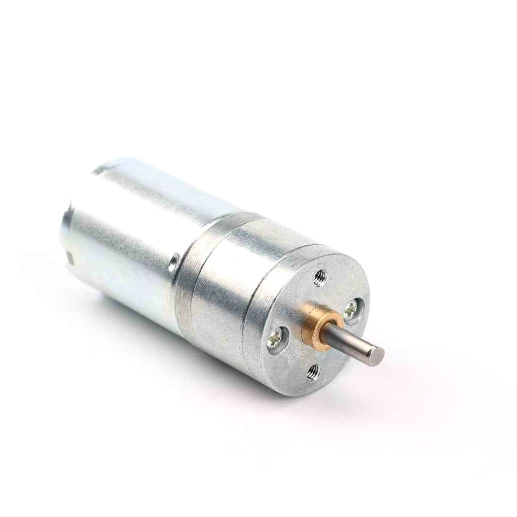
25GA-370 12V 12RPM DC Reducer Gear Motor
A compact geared DC motor perfect for robotics projects — runs at 12V and draws under 600mA running current, compatible with the L293D.
10. Frequently Asked Questions
Q: Can L293D control a BLDC motor?
No. Brushless DC motors require a 3-phase ESC controller with precise commutation timing. The L293D is designed only for brushed DC motors (2-wire), stepper motors, and solenoids. For BLDC motors, you need a dedicated ESC module.
Q: The L293D gets very hot. Is this normal?
Some warmth is normal due to the ~1.4V dropout voltage multiplied by current. If the chip is untouchably hot within seconds, the motor is drawing too much current (exceeding 600 mA), the chip is wired incorrectly, or there is a shoot-through condition. Reduce motor load, add a heatsink to the GND pins, or switch to the L298N for higher-current applications.
Q: What voltage can I use for the motor supply?
The motor supply (VSS, pin 8) can be anywhere from 4.5V to 36V, independent of the logic supply. For 5V motors like the 28BYJ-48, connect both VCC and VSS to 5V. For 12V motors, use 12V for VSS and 5V for VCC (logic).
Q: Can I use 3.3V logic (ESP32/Raspberry Pi) with L293D?
The L293D’s input high threshold is typically 2.3V, so 3.3V logic works reliably. Be aware that 3.3V systems often have lower current output capabilities — use logic-level shifting or buffer ICs if driving multiple pins simultaneously causes issues.
Q: Can I parallel two channels for more current?
Yes. If you only need one motor, you can parallel both H-bridges of the L293D (OUT1 with OUT3, OUT2 with OUT4 — same direction, same enable) to get up to 1.2A continuous. This requires careful symmetrical wiring to share current evenly.
Q: Does the L293D have PWM speed control?
Yes — connect the Enable pins to PWM outputs on your microcontroller. The duty cycle of the PWM signal controls the average voltage across the motor, which controls speed. The direction (IN1/IN2) pins remain static while the Enable pin is PWM-modulated.
Ready to Build Your Motor Circuit?
Shop motors, drivers, and electronics components at Zbotic — fast delivery across India for hobbyists, students and makers.


Add comment