
You have built a sophisticated Arduino project with multiple sensors — a BMP280 for pressure, a DHT20 for humidity, an INA219 for current monitoring, and a second BMP280 for differential pressure measurement. Everything works individually, but when you connect them all to the same I2C bus, chaos ensues: readings are wrong, sensors stop responding, or you get data from the wrong device. You have hit the classic I2C sensor address conflict.
This troubleshooting guide covers exactly how I2C addressing works, why conflicts happen, and every practical method to resolve them — from changing sensor addresses to deploying I2C multiplexers. By the end, you will be able to run as many I2C sensors as your project demands on a single microcontroller.
1. I2C Addressing: How It Works
The Inter-Integrated Circuit (I2C) protocol uses a two-wire bus: SDA (data) and SCL (clock). Every device on the bus has a unique 7-bit address, allowing up to 128 unique addresses (though a few are reserved). When the microcontroller sends a communication, it first transmits the 7-bit device address followed by a read/write bit. Only the device whose address matches responds.
The address range 0x00–0x07 and 0x78–0x7F are reserved, leaving 112 usable addresses in the standard 7-bit range. Many manufacturers also support 10-bit extended addressing, allowing up to 1024 unique addresses, though most hobbyist sensors use 7-bit addressing.
Fixed vs Configurable Addresses
Some sensors have a fixed I2C address hard-coded in the chip. Others expose one or more address selection pins (often labelled ADDR, ADR, or AD0) that you connect to GND or VCC to select between two or four possible addresses. The maximum number of identical sensors on one bus is determined entirely by how many address options the manufacturer provided.
2. Why Address Conflicts Happen
Address conflicts occur when two or more devices on the same I2C bus share the same 7-bit address. This happens in three main scenarios:
Scenario 1: Identical Sensors
You want two BME280 sensors in your project (one inside, one outside). Both have address 0x76 by default. When the master requests data from 0x76, both sensors respond simultaneously — causing data corruption, bus lock-up, or garbage readings.
Scenario 2: Different Sensors, Same Address
Different sensor types can coincidentally share the same address. For example, the PCA9685 PWM driver and some OLED displays both occupy addresses in the 0x3C–0x3F range. Two different sensors from different manufacturers can collide.
Scenario 3: Address After Configuration
You configured a sensor’s address via its ADDR pin, but accidentally set it to the same address as another sensor already on the bus. This is common when adding sensors incrementally to a growing project.
3. Diagnosing an Address Conflict
Symptoms of an I2C address conflict include:
- One or more sensors return incorrect data or zeros
- Sensors respond intermittently (bus contention causes random failures)
- The I2C bus freezes and all sensors stop responding
- An I2C scanner shows fewer devices than expected
- Serial output shows
Sensor not found!for a sensor that you know is connected
Elimination test: Connect each sensor individually and confirm it works. Then add sensors one at a time. When adding a specific sensor causes others to malfunction, that sensor is the conflict source.
4. Running an I2C Scanner
The I2C scanner sketch is the essential first diagnostic tool. It scans all 128 possible addresses and reports which ones respond:
#include <Wire.h>

void setup() {
  Wire.begin();
  Serial.begin(115200);
  Serial.println("I2C Scanner");
  Serial.println("Scanning...");

  int found = 0;
  for (byte addr = 1; addr < 127; addr++) {
    Wire.beginTransmission(addr);
    byte error = Wire.endTransmission();

    if (error == 0) {
      Serial.print("Device found at address 0x");
      if (addr < 16) Serial.print("0");
      Serial.print(addr, HEX);
      Serial.println(" !");
      found++;
    } else if (error == 4) {
      Serial.print("Unknown error at address 0x");
      if (addr < 16) Serial.print("0");
      Serial.println(addr, HEX);
    }
  }

  if (found == 0) Serial.println("No I2C devices found!");
  else { Serial.print(found); Serial.println(" device(s) found."); }
}

void loop() {}
Run this with each combination of sensors to map your I2C address space. If you see fewer addresses than expected, two devices are sharing an address and only one is responding.
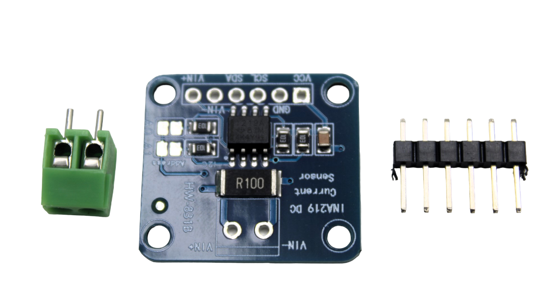
CJMCU-219 INA219 I2C Bi-directional Current/Power Monitoring Module
The INA219 supports four I2C addresses via A0/A1 pins — a great example of a sensor with built-in address conflict resolution for multi-sensor setups.
5. Method 1: Hardware Address Selection Pins
The simplest fix — when available — is to use the sensor’s address selection pins. Most I2C sensors expose one or two address bits as physical pins.
Single ADDR Pin (2 Addresses)
Sensors like the BMP280 and AMG8833 have one address pin providing two options:
- ADDR/ADR pin → GND: Address 0x76 (BMP280) or 0x68 (AMG8833)
- ADDR/ADR pin → VCC: Address 0x77 (BMP280) or 0x69 (AMG8833)
This allows you to use exactly two identical sensors on the same bus.
Dual Address Pins (4 Addresses)
Sensors like the INA219 (A0 and A1 pins) and ADS1115 provide four possible addresses by connecting each pin to GND or VCC:
| A1 Pin | A0 Pin | I2C Address |
|---|---|---|
| GND | GND | 0x40 |
| GND | VCC | 0x41 |
| VCC | GND | 0x44 |
| VCC | VCC | 0x45 |
Some sensors (like the TMP102) even allow connecting the address pin to SDA or SCL, giving four possible values from a single pin.
6. Method 2: I2C Multiplexer (TCA9548A)
When you need more than two identical sensors, or sensors with fixed addresses that conflict, an I2C multiplexer is the solution. The TCA9548A is the most popular choice — it provides 8 independent I2C channels on a single bus.
How the TCA9548A Works
The TCA9548A connects to your Arduino’s main I2C bus and has its own I2C address (0x70–0x77, selectable via A0/A1/A2 pins). You communicate with the multiplexer to select which of its 8 downstream channels is active. Only the selected channel is electrically connected to the main bus — all other channels are isolated. This means each channel can have sensors with the same address, because only one channel is ever active at a time.
TCA9548A Wiring
| TCA9548A Pin | Arduino Uno |
|---|---|
| VCC | 3.3V or 5V |
| GND | GND |
| SDA | A4 (SDA) |
| SCL | A5 (SCL) |
| A0, A1, A2 | GND (for address 0x70) |
| SD0–SD7 / SC0–SC7 | Connect individual sensors |
TCA9548A Channel Selection Code
#include <Wire.h>

#define TCA_ADDR 0x70

void tcaSelect(uint8_t channel) {
  if (channel > 7) return;
  Wire.beginTransmission(TCA_ADDR);
  Wire.write(1 << channel); // Enable only the selected channel
  Wire.endTransmission();
}

void tcaDisableAll() {
  Wire.beginTransmission(TCA_ADDR);
  Wire.write(0); // Disable all channels
  Wire.endTransmission();
}

void setup() {
  Wire.begin();
  Wire.setClock(400000); // Fast mode I2C
  Serial.begin(115200);
}

void loop() {
  // Read sensor on channel 0
  tcaSelect(0);
  // ... read first BMP280 (address 0x76)

  // Read sensor on channel 1
  tcaSelect(1);
  // ... read second BMP280 (also address 0x76 — no conflict!)

  tcaDisableAll(); // Disable when done
  delay(1000);
}
7. Method 3: Software I2C on Different Pins
Arduino supports software (bit-banged) I2C using any two GPIO pins via the SoftWire or SoftI2CMaster libraries. This creates a second independent I2C bus without requiring additional hardware.
#include <Wire.h>       // Hardware I2C on A4/A5
#include <SoftWire.h>  // Software I2C on any pins

const int SOFT_SDA = 8;
const int SOFT_SCL = 9;
SoftWire softWire(SOFT_SDA, SOFT_SCL);

void setup() {
  Wire.begin();     // Hardware I2C bus
  softWire.begin(); // Software I2C bus

  // Sensor A on hardware I2C (address 0x76)
  // Sensor B on software I2C (also address 0x76 — no conflict!)
}
Limitations of Software I2C: Maximum speed is typically 100 kHz (standard mode), as opposed to 400 kHz for hardware I2C. It also uses more CPU cycles. Suitable for slow-polling sensors but not high-speed data acquisition.
8. Method 4: Hardware I2C Buses (ESP32 / STM32)
The ESP32 has two hardware I2C controllers, allowing two completely independent I2C buses. STM32 microcontrollers often have 3 or more. This is the highest-performance solution when your microcontroller supports it:
// ESP32: Two hardware I2C buses
#include <Wire.h>

TwoWire I2C_A = TwoWire(0); // First hardware I2C controller
TwoWire I2C_B = TwoWire(1); // Second hardware I2C controller

void setup() {
  // Bus A: SDA=21, SCL=22 (ESP32 defaults)
  I2C_A.begin(21, 22, 400000);

  // Bus B: SDA=16, SCL=17 (custom pins)
  I2C_B.begin(16, 17, 400000);

  // Pass the correct Wire object to each sensor library
  // e.g., bmp1.begin(0x76, &I2C_A);
  //        bmp2.begin(0x76, &I2C_B);
}
9. Common Sensors and Their Address Options
| Sensor | Default Address | Alternate Address(es) | Method |
|---|---|---|---|
| BMP280 | 0x76 | 0x77 | SDO pin to VCC |
| BME280 | 0x76 | 0x77 | SDO pin to VCC |
| INA219 | 0x40 | 0x41, 0x44, 0x45 | A0/A1 pins |
| SSD1306 OLED | 0x3C | 0x3D | SA0 resistor bridge |
| AMG8833 | 0x68 | 0x69 | AD_SELECT pin |
| MPU6050 | 0x68 | 0x69 | AD0 pin to VCC |
| ADS1115 | 0x48 | 0x49, 0x4A, 0x4B | ADDR pin |
| DS3231 RTC | 0x68 | Fixed (no options) | Use multiplexer |
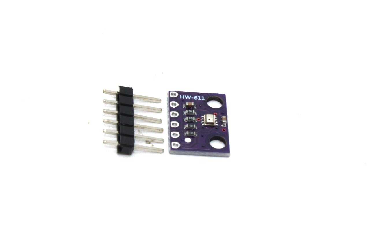
BMP280 Barometric Pressure and Altitude Sensor I2C/SPI Module
The BMP280’s SDO pin lets you select between two I2C addresses — use two of these for differential pressure measurement in the same project without any conflict.
10. I2C Bus Best Practices
Pull-up Resistors
I2C requires pull-up resistors on both SDA and SCL lines to VCC. Most breakout boards include 4.7 kΩ pull-ups. When you connect multiple modules, these resistors parallel together — reducing the effective pull-up resistance. Low pull-up resistance causes excessive current draw and can damage GPIO pins.
Rule of thumb: With more than 3-4 breakout boards on the same bus, remove the pull-up resistors from all but one board, or replace all with a single external 2.2 kΩ resistor.
Bus Capacitance
Long wires increase bus capacitance, slowing signal rise times and causing data errors. The I2C specification limits bus capacitance to 400 pF for standard and fast modes. For long cable runs, use an I2C bus extender like the P82B96 or reduce the I2C clock speed.
I2C Clock Speed
- Standard mode: 100 kHz (most compatible, works with all devices)
- Fast mode: 400 kHz (recommended for multiple sensors to reduce read time)
- Fast-mode Plus: 1 MHz (requires special drivers, rarely needed)
Set clock speed in Arduino: Wire.setClock(400000);
Bus Recovery
I2C buses can get stuck in a state where SDA is permanently pulled low by a sensor that locked up mid-transaction. When this happens, sending 9 clock pulses on SCL (while SDA remains low) frees any stuck sensor. This is known as I2C bus recovery.
11. Advanced Troubleshooting
Bus Lockup Symptoms and Fixes
If your I2C bus completely stops working:
- Power-cycle all devices (including the Arduino) simultaneously
- Check for short circuits between SDA and SCL
- Verify all GND connections are shared
- Check for incorrect voltage — 5V on a 3.3V sensor can cause permanent damage and bus issues
- Implement hardware bus recovery: toggle SCL 9 times with SDA high, then send a STOP condition
Intermittent Failures
- Add 100 nF decoupling capacitors on each sensor’s VCC pin close to the IC
- Shorten I2C wire lengths — every cm adds capacitance
- Ensure adequate power supply — sensors pulling extra current during ADC conversions can cause voltage drops that corrupt I2C communication
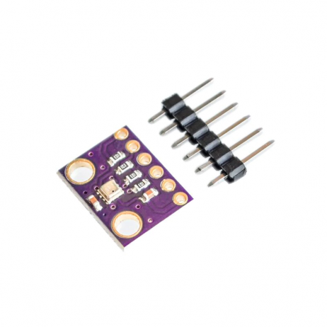
GY-BME280-3.3 Precision Altimeter Atmospheric Pressure Sensor Module
The BME280 combines temperature, humidity, and pressure sensing in one I2C sensor with address selection — minimises the number of devices on your bus.
Frequently Asked Questions
How many I2C devices can I connect to one Arduino?
The I2C protocol supports up to 128 unique 7-bit addresses, so theoretically 128 devices. In practice, the limit is set by bus capacitance and pull-up resistor values. With standard breakout boards, you can typically connect 8–16 devices reliably on a single hardware I2C bus. For more, use a TCA9548A multiplexer or multiple I2C buses (supported on ESP32, STM32).
Can I change a sensor’s I2C address in software?
Generally no. Most I2C sensors have hardware-only address selection through physical pins or resistors. Address selection via software is rare — a few specific sensors (like the LTC4151) allow address programming via a special command sequence, but this is the exception. The standard approach is hardware address pins or an I2C multiplexer.
My I2C scanner shows the sensor but the library says sensor not found — why?
The library may be looking for the sensor at a different address than what you’ve configured. Check whether the library’s begin() function accepts an address parameter. Also verify the sensor’s address matches what the library expects — some libraries have the address hard-coded differently from the sensor’s default. For example, some BMP280 libraries default to 0x77 while the sensor ships set to 0x76.
Is the TCA9548A multiplexer compatible with 5V and 3.3V sensors?
The TCA9548A operates at both 3.3V and 5V and is tolerant of different voltages on different channels when powered appropriately. You can have 5V sensors on some channels and 3.3V sensors on others, provided each channel’s pull-ups match the sensor’s VCC. The TCA9548A provides electrical isolation between channels, making mixed-voltage setups possible with careful design.
Why does my I2C communication work at 100 kHz but fail at 400 kHz?
This indicates excessive bus capacitance — long wires, many parallel pull-up resistors, or many devices on the bus cause slow signal rise times that work at 100 kHz but fail at 400 kHz. Solutions include: shortening I2C wires, removing redundant pull-up resistors, adding an active I2C buffer (like the PCA9515), or reducing the clock speed. Also ensure all your sensors support fast mode — some older sensors only support standard 100 kHz.
Build Complex Multi-Sensor Projects with Confidence
Find I2C sensors, multiplexers, and all the components for your Arduino projects at Zbotic — India’s trusted electronics supplier.


Add comment