
One of the most common mistakes beginners make in electronics projects is directly connecting a 5V Arduino to a 3.3V device without an I2C level shifter. Mixing 5V and 3.3V logic can instantly damage ESP32s, OLED displays, and sensor modules — components that can cost several hundred rupees to replace. This tutorial explains exactly why voltage translation is necessary, how bidirectional level shifter modules work, and gives you tested circuit examples for the most common Indian maker project combinations involving 5V and 3.3V I2C devices.
Why You Cannot Directly Connect 5V and 3.3V I2C Lines
Modern microcontrollers and sensors operate at different logic voltage levels. Arduino Uno and Mega use 5V logic; ESP32, ESP8266, and most modern sensors use 3.3V logic. The problem has two sides:
Damage to 3.3V Devices from 5V Signals
When an Arduino Uno drives an I2C SDA or SCL line HIGH, it pulls it to 5V. A 3.3V device receiving this signal sees a voltage that exceeds its absolute maximum rating (typically 3.6V for the GPIO pins). Over time — or sometimes immediately — this causes latch-up or permanent silicon damage. ESP32 and ESP8266 chips are particularly vulnerable because their GPIO absolute maximum is 3.9V.
Logic Level Incompatibility
Even if a 3.3V device is not damaged, the 5V microcontroller may not correctly read the 3.3V device’s HIGH output. For a 5V Arduino, a logic HIGH input threshold is typically 3.0V (VIH = 0.6 × VCC), so 3.3V is just barely within the valid HIGH range. However, pull-up resistors, capacitance, and signal degradation can push this below the threshold and cause intermittent communication failures.
I2C Pull-Up Resistor Conflict
I2C uses open-drain signalling with pull-up resistors. If you connect a 5V pull-up to an I2C bus shared with a 3.3V device, the bus idle-HIGH voltage is 5V — directly applied to the 3.3V device’s SDA/SCL pins. This is a guaranteed way to destroy your 3.3V sensor or module.
How MOSFET-Based Bidirectional Level Shifters Work
The most elegant solution for I2C level shifting is the bidirectional MOSFET circuit pioneered by NXP (Philips). It uses an N-channel enhancement-mode MOSFET (commonly a BSS138) with pull-up resistors on both the LV (low voltage, 3.3V) and HV (high voltage, 5V) sides.
Here is how it works in each direction:
When the Low-Voltage Side Pulls Low (3.3V device drives LOW)
- The 3.3V device pulls SDA LOW → LV side goes to 0V.
- MOSFET gate (connected to LV_REF = 3.3V) remains at 3.3V above the source (now at 0V), so VGS = 3.3V → MOSFET turns ON.
- MOSFET drain connects HV side to 0V → 5V side SDA also pulled LOW.
When the High-Voltage Side Pulls Low (5V device drives LOW)
- The 5V device pulls SDA LOW → HV side goes to 0V.
- MOSFET body diode conducts from LV side to HV side (LV side also pulled LOW).
- Simultaneously, VGS = 3.3V – 0V = 3.3V → MOSFET turns ON, reinforcing the LOW state.
The result is a fully bidirectional level translator that requires no direction control signal — it automatically senses which side is driving. This is perfect for I2C’s bidirectional open-drain bus.

0.96 Inch I2C IIC OLED LCD Module 4pin White SSD1306 Chip
A popular 3.3V I2C OLED display — a classic use case for level shifters when connecting to a 5V Arduino Uno or Mega.
Types of Level Shifters: Which One to Choose
Several level shifter options exist, each with different trade-offs:
| Type | Bidirectional | Best For | Max Speed |
|---|---|---|---|
| MOSFET (BSS138) | Yes | I2C, UART, SPI | 1 MHz (I2C fast mode) |
| Voltage divider (resistors) | No (one-way) | One-directional signals | ~100 kHz |
| 74HCT logic IC | No (one-way) | High-speed one-way | 25 MHz+ |
| TXS0102/TXB0108 IC | Yes | SPI, UART (NOT I2C*) | 24 MHz |
*Important: TI’s TXS0102 and TXB0108 are NOT suitable for I2C. They use output-enable circuitry that conflicts with I2C’s open-drain protocol. Always use MOSFET-based modules (the SparkFun-style 4-channel bidirectional level shifter) for I2C.
Wiring an I2C Level Shifter: Step-by-Step
A standard 4-channel bidirectional level shifter module (available at Zbotic and most Indian electronics shops) has the following pins:
- LV — Low voltage reference (connect to 3.3V)
- HV — High voltage reference (connect to 5V)
- GND — Common ground (both sides share the same GND)
- LV1, LV2, LV3, LV4 — Low-voltage side channels
- HV1, HV2, HV3, HV4 — High-voltage side channels
For I2C specifically, you use two channels (one for SDA, one for SCL):
| Level Shifter Pin | Connection |
|---|---|
| HV | Arduino 5V |
| LV | 3.3V device VCC |
| GND (both sides) | Common GND |
| HV1 | Arduino SDA (A4 on Uno) |
| LV1 | 3.3V device SDA |
| HV2 | Arduino SCL (A5 on Uno) |
| LV2 | 3.3V device SCL |
Pull-up resistors: Most level shifter modules have 10kΩ pull-up resistors on both sides to LV and HV rails. If your devices also have internal pull-ups (many OLED modules do), you may get a parallel resistance that is too low (e.g., 2.5kΩ) and cause slow rise times. Remove one set of pull-ups for reliable I2C at 400kHz fast mode.
Example: OLED Display with ESP32 (3.3V Only — No Level Shifter Needed)
When both the ESP32 and the OLED module operate at 3.3V, no level shifter is needed. This is actually the most common setup for Indian makers today:
| OLED Pin | ESP32 Pin |
|---|---|
| VCC | 3.3V |
| GND | GND |
| SDA | GPIO21 (default I2C SDA) |
| SCL | GPIO22 (default I2C SCL) |
Simple Arduino sketch to test the connection:
#include <Wire.h>
#include <Adafruit_GFX.h>
#include <Adafruit_SSD1306.h>

#define SCREEN_WIDTH 128
#define SCREEN_HEIGHT 64

Adafruit_SSD1306 display(SCREEN_WIDTH, SCREEN_HEIGHT, &Wire, -1);

void setup() {
  Serial.begin(115200);
  if (!display.begin(SSD1306_SWITCHCAPVCC, 0x3C)) {
    Serial.println("OLED not found at 0x3C!");
    while (true);
  }
  display.clearDisplay();
  display.setTextSize(1);
  display.setTextColor(WHITE);
  display.setCursor(0, 0);
  display.println("I2C Level Shifter");
  display.println("Test: OK!");
  display.display();
}

void loop() {}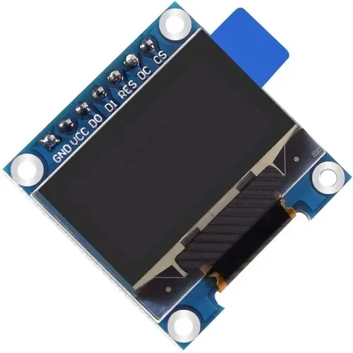
0.96 Inch SPI OLED LCD Module + CSpin 7pin White SSD1306 Chip
Use the SPI variant when you need higher speeds — operates at 3.3V and connects to ESP32 GPIO directly without any level shifting required.
Example: OLED Display with Arduino Uno (5V to 3.3V, Level Shifter Required)
When using a 5V Arduino Uno with a 3.3V OLED, the level shifter goes between them. Many SSD1306 OLED breakout boards sold in India actually have their own 3.3V regulator and level-shifted I2C inputs — check the board’s schematic or markings. If the board says “5V compatible” on I2C, you may not need an external level shifter. If not, use the MOSFET module.
With the level shifter in place, the standard Wire.h I2C code works identically. The level shifter is entirely transparent to software.
After wiring, open Arduino IDE → Tools → I2C Scanner sketch to verify devices are detected:
#include <Wire.h>
void setup() {
  Wire.begin();
  Serial.begin(9600);
  Serial.println("I2C Scanner");
  for (byte addr = 1; addr < 127; addr++) {
    Wire.beginTransmission(addr);
    byte error = Wire.endTransmission();
    if (error == 0) {
      Serial.print("Found device at 0x");
      Serial.println(addr, HEX);
    }
  }
}
void loop() {}
The SSD1306 OLED should appear at address 0x3C (or 0x3D if the ADDR pin is HIGH).

Waveshare ESP32-S3 1.46inch Round Display Development Board 412×412
An all-in-one 3.3V ESP32-S3 board with integrated display, accelerometer, and speaker — no level shifting required, everything runs at 3.3V natively.
Troubleshooting I2C Communication Issues
I2C Scanner Finds No Devices
First check your power and ground connections. Then verify SDA/SCL are not swapped (a very common error). Measure the idle voltage on SDA and SCL with a multimeter — both should read close to VCC when the bus is idle (due to pull-up resistors). If they read 0V, your pull-up resistors are missing or the bus is being held LOW by a damaged device.
Communication Works but Occasionally Drops
This is usually a pull-up resistor value issue. The standard 4.7kΩ pull-up works for 100kHz standard mode. For 400kHz fast mode, reduce to 2.2kΩ. If you have many devices on the bus, parasitic capacitance increases rise time — lower pull-up values help at the cost of higher power consumption.
Level Shifter Gets Hot
This indicates a short circuit or reverse voltage. Verify LV connects to 3.3V (not 5V) and HV connects to 5V (not 3.3V). Swapping these applies 5V to the LV side circuits and destroys the MOSFETs in the module.
Works at 100kHz but Fails at 400kHz
MOSFET-based level shifters are capacitance-limited. Long wires and multiple bus devices increase capacitance. Either reduce pull-up resistors (to 1kΩ–2.2kΩ) or run I2C at 100kHz standard mode. Most sensor projects do not need 400kHz — standard mode is sufficient for 1–10 sensors.
Frequently Asked Questions
Q: Can I use a simple resistor voltage divider as an I2C level shifter?
Only for one-directional signals. Since I2C is bidirectional (both master and slave can drive the bus), a resistor divider only works for signals going from 5V to 3.3V. The 3.3V device cannot drive the 5V side HIGH through a resistor divider. For genuine I2C, always use a bidirectional MOSFET-based level shifter.
Q: Is it safe to connect a 3.3V sensor directly to an ESP32 without a level shifter?
Yes — when both are 3.3V, no level shifting is needed. The ESP32 itself runs at 3.3V. Problems only arise when mixing with 5V devices like Arduino Uno, Arduino Mega, or older 5V sensor modules.
Q: How many I2C devices can I connect to one bus?
The I2C protocol supports up to 128 unique 7-bit addresses (112 usable after reserving special addresses). In practice, the limiting factor is bus capacitance — the total parasitic capacitance should not exceed 400pF. With short PCB traces, you can comfortably connect 10–20 devices on one bus.
Q: Do I need a level shifter between Arduino Mega and ESP32 for UART communication?
Yes, for the TX line from Arduino (5V) to ESP32 RX (3.3V). Use a resistor voltage divider (2kΩ + 3.3kΩ) for one-directional UART TX. The ESP32 TX (3.3V) connecting to Arduino Mega RX does not need shifting — 3.3V is within the Arduino Mega’s 5V input HIGH threshold.
Q: What happens if I accidentally connect a 5V I2C line to a 3.3V ESP32 GPIO?
In a single brief connection, you may get lucky and the chip survives. But each overvoltage event stresses the ESD protection diodes inside the GPIO pad. Repeated exposure causes cumulative degradation and eventual permanent failure of that GPIO pin — or in severe cases, the entire chip. Always use a level shifter; they cost under ₹30 and protect components worth hundreds of rupees.
Protect Your Components — Shop Smart
Get OLED modules, ESP32/ESP8266 boards, and all communication accessories at Zbotic — India’s maker store with genuine components and fast nationwide delivery.


Add comment