
How to Wire a Drone: Complete Wiring Diagram for Beginners (2026 Guide)
Wiring a drone is one of the most intimidating steps for first-time builders. You are looking at a pile of electronic components — a flight controller, four ESCs, four motors, a battery connector, an FPV camera, a video transmitter, and a receiver — and wondering how they all connect together. One wrong connection can fry a component, create a short circuit, or worse, cause an in-flight failure.
The good news is that drone wiring follows a logical, repeatable pattern that becomes second nature after your first build. This guide walks you through every connection in a standard FPV quadcopter, explains why each connection exists, provides a complete wiring diagram description for a typical 5-inch FPV build, and gives you the tools to troubleshoot wiring problems confidently. Whether you are building a 5-inch freestyle quad, a 7-inch long range drone, or a small Tiny Whoop, the fundamental concepts are the same.
1. Overview of Drone Components
Before touching a soldering iron, understand what each component does and how it relates to the wiring:
- Battery: The energy source. Provides DC voltage (typically 14.8V for 4S, 22.2V for 6S) to the entire drone.
- Power Distribution Board (PDB) or 4-in-1 ESC: Distributes battery power to the four individual ESCs. Modern 4-in-1 ESCs combine all four ESCs on one board and also handle power distribution.
- Electronic Speed Controllers (ESC): Convert the DC battery power into three-phase AC to drive brushless motors. Each motor needs its own ESC.
- Brushless Motors: Convert electrical energy into rotational mechanical energy. Three phase wires connect to the ESC.
- Flight Controller (FC): The brain of the drone. Contains the IMU (gyroscope + accelerometer), runs Betaflight/Cleanflight/ArduPilot firmware, and sends motor speed commands to the ESCs via DSHOT protocol.
- FPV Camera: Captures the video feed. Connects to the video transmitter (VTX) via an analog video signal (for traditional FPV).
- Video Transmitter (VTX): Broadcasts the video signal wirelessly on 5.8GHz (or other bands) to the pilot’s goggles.
- Receiver (RX): Receives control signals from the pilot’s radio transmitter and relays them to the flight controller via UART or SBUS.
- GPS Module: Provides position, speed, and heading data to the FC for position hold and Return to Home.
2. Tools and Supplies Needed
- Soldering iron (60W+ temperature-controlled, ideally Hakko FX-888D or similar)
- 60/40 or 63/37 rosin core solder (1.0mm diameter for power pads, 0.5–0.8mm for signal pads)
- Flux paste or flux pen
- Wire stripper
- Heat shrink tubing (various sizes)
- Silicone wire: 12–14AWG for battery leads and motor wires, 22–26AWG for signal wires
- XT60 connector (female for battery leads on the drone, male for battery)
- Multimeter (for continuity testing and voltage checking)
- Smoke stopper (a 12V car bulb in series with the battery lead — protects against shorts on first power-up)
- Helping hands or PCB vice for holding components while soldering
- Isopropyl alcohol (IPA 99%) for flux cleanup
3. The Power System: Battery → PDB/ESC → Motors
The power system is the “main highway” of current in your drone. Understanding it is critical before soldering a single pad.
Battery to PDB/ESC Connection
The battery connects to the main power input pads of the PDB or 4-in-1 ESC using heavy silicone wire (12–14AWG). This connection carries the full current of the drone — potentially 80–200A at maximum throttle on a 5-inch quad. Use thick wire and ensure excellent solder joints with no cold spots.
The polarity is critical: Red wire = positive (+), Black wire = negative (–). Reversing polarity will instantly destroy every electronic component downstream. Double-check before powering up.
Solder an XT60 female connector to the battery lead wires on the drone side. The battery has a male XT60. The female connector is on the drone because the exposed solder contacts face inward, reducing short-circuit risk.
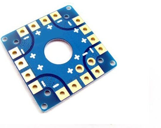
100A Multirotor ESC Power Distribution Battery Board For Quadcopter
A 100A-rated PDB that centralizes power distribution to all four ESCs. Includes capacitor pads and 5V/12V BEC outputs for FC, camera, and VTX power.
Standard Wiring Diagram (Described)
Here is the complete power flow for a standard 5-inch FPV quad with a separate FC and 4-in-1 ESC:
BATTERY (4S LiPo)
    |
    ├── [XT60 Female Connector]
    |
    ↓
4-in-1 ESC (Battery Input Pads: + and –)
    |
    ├── Motor 1 (Front Left, CCW) — 3 phase wires
    ├── Motor 2 (Front Right, CW) — 3 phase wires
    ├── Motor 3 (Rear Right, CCW) — 3 phase wires
    ├── Motor 4 (Rear Left, CW) — 3 phase wires
    |
    ├── ESC Signal Harness → Flight Controller Motor Pads (M1/M2/M3/M4)
    |   (GND + Signal wires, DSHOT protocol)
    |
    └── 5V/9V/12V regulated output → FC 5V input, VTX power, Camera power

FLIGHT CONTROLLER
    |
    ├── UART1 TX/RX → Receiver (ELRS/CRSF)
    ├── UART2 TX/RX → GPS module
    ├── UART3 TX → VTX SmartAudio/Tramp
    ├── Camera video in → OSD video overlay
    ├── Camera video out → VTX video in
    └── USB port → Betaflight Configurator
4. Motor Wiring and Direction
Brushless motors have three phase wires (usually coloured black, red/blue, yellow — but colours are not standardised). Connect these to the three ESC motor output pads. The order does not matter initially — motor direction is set in Betaflight using the Motor tab or BLHeli Suite, and you simply flip the direction digitally if a motor spins the wrong way.
Standard Motor Layout (Betaflight Default)
    Front
    ┌─────────────────┐
    │  CW(2) CCW(1)   │
    │     [FC/ESC]    │
    │  CCW(3) CW(4)   │
    └─────────────────┘
    Rear

1 = Front Left = CCW (counter-clockwise)
2 = Front Right = CW (clockwise)
3 = Rear Right = CCW
4 = Rear Left = CW
Propellers must match motor spin direction — use CW props on CW motors, CCW props on CCW motors. Installing the wrong prop type causes the drone to flip immediately on takeoff.
5. ESC to Flight Controller Wiring
The ESC communicates with the flight controller via a signal protocol. Modern builds use DSHOT (digital) protocol, which is far superior to the old analog PWM protocol:
- DSHOT150/300/600/1200: Digital, no calibration needed, no signal noise. DSHOT600 is the standard for most modern ESCs and FCs.
- Connection: Each ESC motor pad needs a Signal wire and a GND wire connected to the corresponding motor pad on the FC (M1, M2, M3, M4).
- 4-in-1 ESC harness: A single ribbon cable or JST harness carries all four signal wires + GND from the 4-in-1 ESC to the FC. Much neater than individual wires.
6. Regulated Power: BEC, 5V, and 9V Rails
The flight controller, FPV camera, and VTX cannot run directly on 16V (4S) battery voltage — they need regulated lower voltages. This is where the BEC (Battery Eliminator Circuit) comes in.
- 5V rail: Powers the FC, receiver, and some cameras. Usually provided by the 4-in-1 ESC or an onboard linear/switching regulator on the FC.
- 9V or 12V rail: Powers FPV cameras and VTXs that prefer higher voltage for better image quality or stable video output. Some FCs provide this; otherwise use a separate 12V BEC.
- Unregulated battery voltage rail (Vbat): Some FPV cameras and VTX can run directly on battery voltage. Check the component’s datasheet to confirm its operating voltage range.
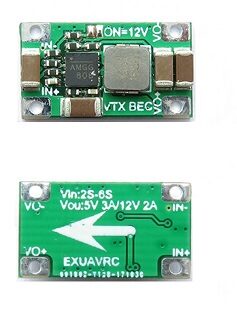
2-6S 5V 5A BEC For Quadcopter Drone
Switching BEC rated at 5V/5A output from 2S–6S input. Provides clean regulated 5V power for flight controllers, servos, and FPV cameras without voltage ripple.
7. FPV Camera and Video Transmitter Wiring
The FPV video chain connects as follows:
FPV Camera
    Power: 5V or 9V (from FC or BEC)
    GND: Common ground
    Video OUT → FC OSD Video IN (for OSD overlay)

Flight Controller
    Video IN (from camera) → OSD processing → Video OUT

Video Transmitter (VTX)
    Power: 5V, 9V, or Vbat (check datasheet)
    GND: Common ground
    Video IN: from FC Video OUT
    SmartAudio/Tramp: to FC UART TX (for VTX power/channel control from OSD)
    RF OUT: to antenna (via SMA or MMCX connector)

1/3″ CMOS 700TVL Mini FPV Camera PAL/NTSC
Compact analog FPV camera suitable for 5-inch and 7-inch FPV builds. Wide dynamic range handles outdoor lighting variation. PAL/NTSC switchable via OSD menu button.
8. Receiver Wiring
The receiver (RX) connects to the flight controller via a UART (serial port). For ELRS/CRSF protocol:
- RX TX → FC UART RX (receive data from RX to FC)
- RX RX → FC UART TX (send data from FC to RX for bidirectional telemetry)
- RX VCC → FC 5V pad
- RX GND → FC GND pad
In Betaflight, configure the UART port for “Serial RX” in the Ports tab, and set the Serial Receiver Provider to CRSF in the Receiver tab.
9. GPS Module Wiring
GPS modules connect via UART (typically UART2 or UART3 on most FCs):
- GPS TX → FC UART RX
- GPS RX → FC UART TX (optional if compass I2C is not needed via UART)
- GPS VCC → FC 5V or 3.3V (check GPS module specs — most are 5V but some are 3.3V)
- GPS GND → FC GND
- Compass SDA → FC I2C SDA (for magnetometer, if your GPS has a built-in compass)
- Compass SCL → FC I2C SCL
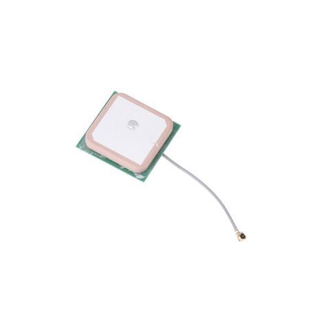
25x25x8mm 28dB High Gain GPS Antenna for NEO-6M/7M/8M
Active GPS patch antenna with 28dB LNA gain. Compatible with NEO-6M, NEO-7M, and NEO-8M GPS modules. Accelerates satellite acquisition in open and semi-urban environments.
10. The Capacitor: Why It Matters
One of the most important — and most overlooked — wiring components is the bulk capacitor. Brushless motors, when decelerating rapidly, can generate large voltage spikes that travel back through the wiring and damage the ESCs and FC. A 35V 1000–2200μF electrolytic capacitor soldered directly across the battery input pads of the ESC suppresses these spikes.
- Value: 1000μF for 4S builds, 1000–2200μF for 6S builds.
- Voltage rating: At least 35V for 4S (16.8V max), at least 50V for 6S (25.2V max). Higher rating is always safe.
- Polarity: The capacitor has a positive and negative lead — do not reverse it. The negative side is usually marked with a white stripe.
- Placement: Mount as close to the ESC battery input pads as possible. Some pilots solder it directly to the XT60 connector leads.
11. Building a Clean Wiring Harness
Clean wiring is not just aesthetics — it reduces weight, prevents interference, and makes maintenance far easier. Follow these practices:
- Use the shortest possible wire lengths. Measure twice, cut once. Excess wire adds weight and creates loops that can catch air or vibrate.
- Twist signal wire pairs. Twist the TX and RX wires of each UART pair together to reduce EMI pickup.
- Route power and signal wires separately. Keep high-current motor and battery wires away from sensitive FC signal wires to reduce electromagnetic interference.
- Heat shrink everything. Every solder joint should be covered with heat shrink. Every exposed wire end should be tinned and protected.
- Tie down wires with zip ties or kapton tape. Free-floating wires can vibrate into moving propellers with catastrophic results.
- Label your wires with a marker or use coloured wire — it saves time during troubleshooting.
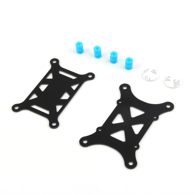
Anti-Vibration Shock Absorber for APM/KK/MWC/Pixhawk
Silicone shock absorber mounting pad for flight controllers. Reduces high-frequency vibration transmission from motors to the FC IMU, improving flight stability and reducing gyro noise.
12. Pre-flight Testing and Smoke Stopper
Before connecting the battery directly for the first time, build or buy a smoke stopper. A smoke stopper is a device with a light bulb wired in series with the battery. If there is a short circuit, the bulb glows bright and limits current — preventing damage to your electronics. Once you confirm no short, you remove the smoke stopper and connect directly.
Step-by-step first power-up procedure:
- Visually inspect all solder joints — look for bridges (unintended connections between pads), cold joints (dull, grainy appearance), and missed connections.
- Use a multimeter in continuity mode to check that + and – of the battery input pads are NOT connected to each other (no short).
- Connect via smoke stopper. If the bulb stays off, you are good. If it lights up, you have a short — find and fix it.
- Power on and check voltages: confirm 5V on the FC 5V rail, check that the FC boots (LED activity), verify that the VTX starts transmitting (check on your goggles).
- In Betaflight Configurator, confirm the receiver is outputting channel data (move your sticks and watch the channel bars move).
- Spin up each motor individually in the Betaflight Motors tab (with props OFF!) and confirm direction. Reverse any motors that spin the wrong way using the DSHOT command in the Motors tab.
- Install props, arm the drone, and perform a short hover test.
13. Common Wiring Mistakes
- Reversed polarity on the battery input: The most common destructive mistake. Always double-check + and – before first power-up.
- Swapping UART TX/RX: The FC’s TX connects to the receiver’s RX, and vice versa. Connecting TX→TX or RX→RX means no communication.
- Powering the receiver from an unreliable 5V source: If the FC’s 5V rail sags under load, the receiver can drop out mid-flight causing a failsafe. Use a dedicated BEC for the receiver on larger builds.
- Forgetting the capacitor: ESC failures are often caused by voltage spikes that a bulk capacitor would have suppressed.
- Too-long or loose wires near propellers: Always secure wires and confirm clearance from all spinning components before each flight.
- Wrong prop orientation: CW and CCW props look similar but have a different blade pitch angle. Install the wrong prop and the motor pushes down instead of up.
- Cold solder joints on motor pads: High-vibration motor connections need excellent solder joints. A cold joint creates resistance that heats up during flight and eventually fails.
Frequently Asked Questions
Soldering is strongly recommended for all power connections (battery lead, motor wires to ESC). Connectors add weight, resistance, and potential failure points under the vibration and current demands of flight. Signal wire connections using JST or servo connectors are acceptable.
For a 5-inch build, use 20AWG silicone wire for motor phase connections. For battery leads and main power input, use 12–14AWG. The higher the current, the lower the AWG number (thicker wire) you need.
This is almost always a motor direction problem. One or more motors is spinning the wrong way. Land immediately, go to Betaflight Motors tab (props off), check each motor direction, and use DSHOT commands to reverse the direction of any incorrect motors.
SBUS is an analog serial protocol used by FrSky receivers. CRSF is TBS Crossfire’s bidirectional digital protocol, also used by ExpressLRS. CRSF is faster, bidirectional (supports telemetry back to the TX), and has better noise immunity than SBUS.
Noisy FPV video is almost always caused by unfiltered power to the camera or VTX. Add an LC filter (low-pass filter) between the battery/BEC and the camera/VTX power input. Alternatively, power your camera from the FC’s filtered 5V or 9V rail.
Get All Drone Wiring Components at Zbotic
Zbotic stocks ESCs, PDBs, BECs, FPV cameras, GPS modules, and all the wiring accessories you need to build your drone. Fast shipping across India with expert support.


Add comment