
Most stepper motor tutorials assume you have an Arduino or microcontroller to generate the step pulses. But what if you just want to spin a stepper motor for a simple automation task, a test fixture, or a prototype without writing a single line of code? The EasyDriver — and its underlying approach of standalone stepper motor control — makes this entirely possible.
In this guide, we explain what the EasyDriver is, how it works, and how to run a stepper motor without any microcontroller using only a pulse source. We also cover the wiring for Arduino-controlled operation for those who want both options, and explain the key concepts of microstepping that make stepper drivers so powerful.
1. What Is the EasyDriver?
The EasyDriver is a stepper motor driver board designed by Brian Schmalz, built around the Allegro A3967SLB microstepping driver IC. It is one of the most popular entry-level stepper driver boards in the maker community because of its simplicity, low cost, and clear labelling.
Key features:
- Motor voltage: 7 V – 30 V
- Motor current: Up to 750 mA per phase (adjustable)
- Microstepping: Full, half, quarter, eighth step modes
- Onboard 5V regulator: Can power Arduino from the same supply
- Step/Direction interface: Works with any pulse source — 555 timer, Arduino, FPGA, PLC, or manual button
- Automatic current reduction: Drops to 30% current when idle (reduces heating)
The EasyDriver accepts two logic signals: STEP (each rising edge advances the motor one microstep) and DIR (HIGH = clockwise, LOW = counterclockwise). That is all you need. Any device — or even a manual button — that can produce logic-level pulses can drive this board.
2. Stepper Motor Basics
A stepper motor divides a full 360° rotation into a fixed number of equal steps. Most common stepper motors are bipolar two-phase motors with:
- 200 steps per revolution = 1.8° per full step (most common, e.g., NEMA 17)
- 400 steps per revolution = 0.9° per full step (higher resolution variants)
The motor has two coil windings (phases). By energising these coils in sequence, the rotor aligns with each magnetic pole in turn, creating rotational motion. The sequence and polarity of the coil energisation determines direction and position.
Unlike DC motors, steppers hold their position when powered — they do not need encoder feedback for position control. This makes them ideal for:
- 3D printer axes
- CNC router axes
- Camera sliders
- Telescope mounts
- Precision linear actuators
- Automated turntables and rotary stages
The main disadvantage: if the load exceeds the motor’s torque at any step, the motor skips steps (loses position) without any error indication. This is called stalling, and the driver cannot detect it in open-loop mode.

NEMA17 5.6 kg-cm Stepper Motor – D-Type Shaft
High-torque NEMA 17 bipolar stepper motor compatible with EasyDriver, A4988, and TMC2208 drivers. Detachable cable for easy installation.
3. EasyDriver Pinout & Specs
The EasyDriver board has clearly labelled pads/headers on both edges:
Motor Side (left edge)
- A+ / A– — Motor coil A (winding 1)
- B+ / B– — Motor coil B (winding 2)
- GND — Ground
- M+ — Motor power supply (7–30 V)
Control Side (right edge)
- STEP — Step pulse input (rising edge = one microstep). Active HIGH.
- DIR — Direction. HIGH = one direction, LOW = other direction.
- MS1 / MS2 — Microstep select (see microstepping table)
- RST — Reset input (active LOW). Tie to SLP or HIGH for normal operation.
- SLP — Sleep input (active LOW). Tie HIGH (to 5V) to keep driver awake.
- ENABLE — Enable input (active LOW). Tie LOW or leave floating to enable driver.
- PFD — Decay mode select (fast/slow decay). Usually left at default.
- 5V — 5V output from onboard regulator. Can power a small Arduino.
- GND — Logic ground
4. Running a Stepper Without Arduino
To run a stepper motor using the EasyDriver without any microcontroller, you need just three things:
- A pulse source — anything that produces a TTL-level square wave on the STEP pin
- A direction signal — a simple jumper (HIGH for CW, LOW for CCW)
- Power supply — 7–30V for the motor, and 5V logic from the EasyDriver’s onboard regulator
Minimum standalone wiring:
- M+ → 12V power supply positive
- GND (motor side) → 12V supply negative
- SLP → 5V output (keep awake)
- RST → 5V output (no reset)
- ENABLE → GND (keep enabled)
- DIR → GND (counterclockwise) or 5V (clockwise) — use a jumper wire
- STEP → your pulse source
- A+, A–, B+, B– → motor coil wires
With this wiring, every pulse on the STEP pin rotates the motor by exactly one microstep. At eighth-step mode (default), that is 1/8 of 1.8° = 0.225° per pulse. A full revolution requires 1600 pulses.
5. Manual Pulse Sources: 555 Timer & Push Button
Option A: Push Button Stepping
The simplest possible pulse source: connect a normally-open push button between 5V and the STEP pin, with a 10 kΩ pull-down resistor from STEP to GND. Each button press (rising edge when released due to pull-down) advances the motor one microstep.
This is excellent for testing motor wiring and direction without any code. Press rapidly to spin the motor; release to stop. No debounce is needed because the EasyDriver only triggers on rising edges and a clean push button produces clean enough edges for slow manual stepping.
Option B: 555 Timer Oscillator
For continuous rotation at a fixed speed, a 555 timer in astable mode is the classic solution. Configure the 555 as follows:
- Supply: 5V (from EasyDriver’s 5V output)
- Resistors: R1 = 1 kΩ, R2 = variable (10 kΩ pot)
- Capacitor: C = 1 µF
- Frequency output: Approximately 1–70 Hz depending on pot position
The frequency formula for the 555 astable mode:
f = 1.44 / ((R1 + 2×R2) × C)
At 1 µF cap and R2 = 5 kΩ (mid pot): f ≈ 130 Hz = 130 microsteps/sec = ~4.9 RPM at 1/8 step mode. Rotate the pot clockwise to increase speed.
Connect the 555 output (pin 3) directly to the EasyDriver STEP pin. No resistor needed. Add a 100 µF cap between 5V and GND near the 555 to prevent motor noise from resetting the timer.
Option C: Signal Generator / Function Generator
If you have a function generator or a signal generator module, set it to a square wave output at 5V amplitude, 50% duty cycle. Plug it into the STEP pin. This gives you precise, adjustable speed control from 1 Hz (very slow) to the maximum step frequency (around 20 kHz for most drivers, though motor torque drops at high frequency).
6. Wiring EasyDriver with Arduino
When you do want Arduino control, the EasyDriver connection is minimal:
- STEP → Arduino digital pin 3 (or any digital pin)
- DIR → Arduino digital pin 2
- GND → Arduino GND
- Motor power → separate 12V supply (GND shared with Arduino)
- SLP, RST → tie together and to 5V
// EasyDriver + Arduino — Basic Stepper Control
#define STEP_PIN 3
#define DIR_PIN  2

void setup() {
  pinMode(STEP_PIN, OUTPUT);
  pinMode(DIR_PIN, OUTPUT);
}

void stepMotor(int steps, int delayMicros, bool direction) {
  digitalWrite(DIR_PIN, direction ? HIGH : LOW);
  for (int i = 0; i < steps; i++) {
    digitalWrite(STEP_PIN, HIGH);
    delayMicroseconds(delayMicros);
    digitalWrite(STEP_PIN, LOW);
    delayMicroseconds(delayMicros);
  }
}

void loop() {
  stepMotor(1600, 500, true);   // One CW revolution at ~625 steps/sec
  delay(500);
  stepMotor(1600, 500, false);  // One CCW revolution
  delay(500);
}
The delayMicroseconds(500) gives a step frequency of 1000 Hz = 1600 steps/revolution → ~37 RPM at 1/8 step. Reduce the delay to increase speed (minimum practical ~100 µs = 10 kHz).
7. Microstepping: Quarter, Eighth Step
The EasyDriver’s MS1 and MS2 pins select the microstepping resolution:
| MS1 | MS2 | Mode | Steps/Rev (NEMA17) | °/Step |
|---|---|---|---|---|
| LOW | LOW | Full step | 200 | 1.8° |
| HIGH | LOW | Half step | 400 | 0.9° |
| LOW | HIGH | Quarter step | 800 | 0.45° |
| HIGH | HIGH | Eighth step (default) | 1600 | 0.225° |
The EasyDriver defaults to eighth-step mode (MS1 and MS2 are pulled HIGH by onboard resistors). Eighth-step gives the smoothest motion and lowest vibration but requires 8× more pulses per revolution. For high-speed applications or slower control sources, switch to half or full step to reduce the pulse rate requirement.
Note that at full-step mode, motor torque is approximately 30% less than rated due to only one coil being fully energised at a time. Half-step mode energises both coils alternately, giving the best torque-to-smoothness balance.
8. Adjusting Motor Current
The EasyDriver has a small trimmer potentiometer near the A3967 chip for setting the maximum coil current. This is critical — too low and the motor stalls; too high and the driver and motor overheat.
To set current:
- Power the board without the motor connected first
- Measure the voltage at the POT wiper (test point marked on some boards) relative to GND
- The relationship is approximately:
I_peak = Vref / 0.5(check your board revision) - For a NEMA 17 rated at 1.0A, set Vref ≈ 0.5V (for 1.0A peak)
- For a 28BYJ-48 at 0.2A, set Vref ≈ 0.1V
After setting, connect the motor and briefly touch each coil wire to verify even holding current with no oscillation. A motor that buzzes or oscillates when held still usually has current set too high or a wiring fault.
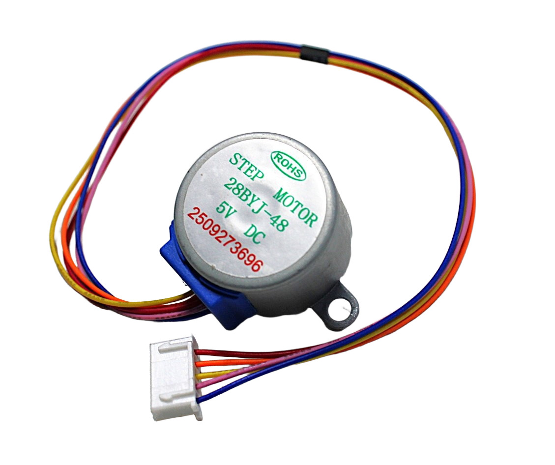
28BYJ-48 5V Stepper Motor
Compact unipolar stepper motor for learning. Can be modified to run as a bipolar motor with EasyDriver by removing the center-tap connection.
9. Recommended Stepper Motors
NEMA17 5.6 kg-cm Stepper Motor – D-Type Shaft
The most commonly used stepper for 3D printers, CNC machines and automation. D-type shaft fits standard pulleys without set-screw slipping.

A4988 Stepper Motor Driver Controller Board
A versatile step/direction driver similar to EasyDriver, supports up to 2A and 1/16 microstepping. A great upgrade path from EasyDriver.
10. Frequently Asked Questions
Q: Can I use EasyDriver for a 28BYJ-48 unipolar stepper?
The 28BYJ-48 is a unipolar motor, but it can be converted to bipolar operation by removing the red centre-tap wire connection inside the motor housing (or ignoring it) and connecting only the four phase wires (Orange, Yellow, Pink, Blue) to EasyDriver A+, A–, B+, B–. The motor will work well with current set to around 200 mA.
Q: What is the maximum RPM with EasyDriver?
At eighth-step mode, the A3967 can handle up to about 10 kHz step rate, giving approximately 375 RPM for a 200-step NEMA 17. In practice, motor torque drops significantly above 3–4 RPM under load. For high-speed applications, use full or half-step mode and a higher-current driver like the A4988 or DRV8825.
Q: Does the motor hold position when the pulses stop?
Yes. When the STEP pin stops receiving pulses, the EasyDriver keeps the coils energised at 30% of the set current (sleep/auto-standby mode). The motor holds its position with reduced holding torque. To maximise holding torque, set the SLP pin HIGH permanently and do not let the driver enter sleep mode.
Q: My motor vibrates but doesn’t rotate. What’s wrong?
This is almost always a wiring problem. Either one or both coil pairs are wired incorrectly (A+ connected to B wire, or polarity reversed within a coil). Use a multimeter to identify the two coil pairs: any two wires with ~4–8 Ω resistance between them belong to the same coil. Wire one pair to A+/A– and the other to B+/B–.
Q: Can I use a 9V battery to power the EasyDriver?
A standard 9V PP3 alkaline battery can technically supply the correct voltage but has very limited current capacity (typically under 500 mA before voltage sags). For even a small NEMA 17, motor current peaks can exceed this. Use a dedicated regulated DC power supply or a multi-cell Li-ion pack for reliable operation.
Q: Is EasyDriver better than A4988?
They target slightly different use cases. The EasyDriver is a full breakout board with onboard 5V regulator, clearly labelled connectors, and a very gentle learning curve — ideal for first-time stepper users. The A4988 is a smaller module with higher current (2A vs 750 mA), no 5V regulator, and is the standard for 3D printers. For learning standalone stepper control, EasyDriver is easier. For production 3D printer or CNC projects, A4988 or TMC2208 are preferred.
Build Your Stepper Motor Project Today
Shop NEMA 17 stepper motors, A4988 drivers, and all the components you need at Zbotic — India’s trusted electronics store for makers.


Add comment