
The Hall effect sensor is one of the most versatile and underappreciated components in electronics. Named after Edwin Hall who discovered the underlying physics in 1879, these sensors detect magnetic fields with no moving parts, no contact, and no wear. They are silent, fast, and reliable for millions of cycles — which is why you find them in car ABS systems, brushless motor controllers, bicycle computers, industrial encoders, and smartphone flip-cover detectors.
For Arduino makers in India, Hall effect sensors are the go-to solution for RPM measurement, proximity detection without contact, position sensing in rotating machinery, and current measurement in power circuits. This comprehensive guide covers the physics, the different types of modules available, complete wiring diagrams, Arduino code examples, and real project ideas you can build today.
1. How the Hall Effect Works
When a current-carrying conductor is placed in a magnetic field perpendicular to the current flow, the magnetic force (Lorentz force) deflects the charge carriers to one side of the conductor. This creates a voltage difference across the width of the conductor — the Hall voltage. The magnitude of this Hall voltage is proportional to the magnetic flux density (field strength).
In a Hall effect sensor IC, a thin semiconductor crystal replaces the conductor. The Hall voltage is amplified, temperature-compensated, and either compared against a threshold (digital output) or buffered directly (analog output). The result is a solid-state magnetic field detector with no mechanical parts.
Key Properties
- Non-contact detection: No mechanical contact means zero wear and infinite cycle life
- Fast response: Digital Hall sensors switch in microseconds — detect magnetic fields at tens of thousands of RPM
- Temperature stable: Good Hall ICs operate from -40 deg C to +150 deg C
- Polarity sensitive: Most digital Hall sensors respond to only one magnetic pole (usually South, by convention)
- Operate through barriers: Works through plastics, aluminium, stainless steel — anywhere a magnet can be sensed
2. Types of Hall Effect Sensors
Unipolar Hall Switch
The most common type in maker modules. The output goes LOW when the South pole of a magnet is brought close (above the threshold field strength) and returns HIGH when the magnet is removed. Examples: A3144, 3144E, OH090U. These respond only to one pole.
Bipolar Hall Latch
Output goes LOW when the South pole is presented and STAYS LOW even when the magnet is removed. It only resets when the North pole is presented. Used in position latching, power-switch actuation, and motor commutation. Examples: SS441A, AH1887.
Omnipolar Hall Switch
Responds to either magnetic pole. When any sufficiently strong magnetic field is detected (regardless of polarity), the output goes LOW. Useful when you cannot control the orientation of a rotating magnet. Example: US1881.
Linear (Analog) Hall Sensor
The output voltage varies linearly with the magnetic flux density. At zero field, output is typically VCC/2 (ratiometric output). Moving a North pole toward the sensor raises the output voltage; South pole lowers it. Used for measuring current, detecting magnetic proximity with graduated response, and measuring linear or rotary position. Examples: A1302, A1324, SS495A.
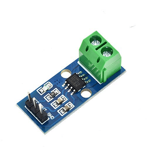
Current Sensing Hall Sensor (ACS712)
Specialized Hall sensors purpose-designed for current measurement. The conductor whose current you are measuring passes through a ferrite core that concentrates the magnetic field onto the Hall element. Output is a voltage proportional to current. Popular modules: ACS712-05B (5A), ACS712-20A (20A), ACS712-30A (30A).
3. Common Hall Sensor Modules in India
- KY-003 / A3144 Digital Hall Sensor Module: 3-pin module (VCC, GND, Signal), digital output, works with 5 V Arduino directly. Onboard LED indicates detection. Rs 20-50.
- KY-035 Analog Hall Module: Analog output proportional to field strength. Connect Signal to an analog pin. Rs 30-60.
- ACS712 Current Sensor (5A/20A/30A): Hall-based current sensor module. Rs 80-150.
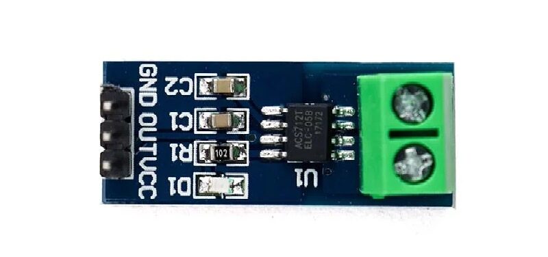
5A Range Current Sensor Module ACS712
Hall-effect based current sensor — measure DC and AC current up to 5A with +/-1.5% accuracy and full isolation from your Arduino circuit.
4. Wiring Hall Effect Sensors to Arduino
Digital Hall Sensor (KY-003 / A3144 Module)
Hall Module  -->  Arduino Uno
VCC          -->  5V
GND          -->  GND
S (Signal)   -->  Digital Pin 2 (or any digital pin)

// Output: LOW = magnet detected; HIGH = no magnet
Use an internal pull-up resistor (pinMode(2, INPUT_PULLUP)) if your module does not include one — some bare A3144 chips require an external 10 kOhm pull-up from output to VCC.
Analog Hall Sensor (A1302 Module)
Analog Hall Module  -->  Arduino Uno
VCC                 -->  5V
GND                 -->  GND
S (Signal)          -->  A0 (Analog Pin)

// Output: ~512 ADC counts at zero field (2.5V)
//         >512 = North pole approaching
//         <512 = South pole approaching
ACS712 Current Sensor
ACS712 Module  -->  Arduino Uno
VCC            -->  5V
GND            -->  GND
OUT            -->  A1 (Analog Pin)
IP+, IP-       -->  In series with the load circuit being measured

// ACS712-05B: 185 mV/A sensitivity, zero-current output = 2.5V
// ACS712-20A: 100 mV/A sensitivity
// ACS712-30A: 66 mV/A sensitivity
5. Arduino Code: Basic Magnet Detection
const int hallPin = 2;
const int ledPin  = 13;

void setup() {
  Serial.begin(9600);
  pinMode(hallPin, INPUT_PULLUP);
  pinMode(ledPin, OUTPUT);
  Serial.println("Hall Effect Sensor Ready");
  Serial.println("Bring a magnet close to the sensor...");
}

void loop() {
  int state = digitalRead(hallPin);

  if (state == LOW) {
    digitalWrite(ledPin, HIGH);
    Serial.println("MAGNET DETECTED!");
  } else {
    digitalWrite(ledPin, LOW);
  }
  delay(50);
}
6. Arduino Code: RPM Measurement
Measuring RPM is one of the most popular Hall sensor applications. Attach a small neodymium magnet to a rotating shaft or wheel. Each time the magnet passes the sensor, it triggers an interrupt. Count pulses per second and convert to RPM.
const int hallPin = 2; // Must be interrupt-capable pin (2 or 3 on Uno)
volatile unsigned long pulseCount = 0;
unsigned long lastTime = 0;
float rpm = 0;

void hallISR() {
  pulseCount++;
}

void setup() {
  Serial.begin(9600);
  pinMode(hallPin, INPUT_PULLUP);
  attachInterrupt(digitalPinToInterrupt(hallPin), hallISR, FALLING);
  lastTime = millis();
  Serial.println("RPM Meter Ready");
}

void loop() {
  unsigned long currentTime = millis();
  unsigned long elapsed = currentTime - lastTime;

  if (elapsed >= 1000) {
    noInterrupts();
    unsigned long count = pulseCount;
    pulseCount = 0;
    interrupts();

    // RPM = pulses/second x 60 divided by magnets_per_revolution
    // For 1 magnet: RPM = count x 60
    rpm = (count * 60.0) / (elapsed / 1000.0);

    Serial.print("RPM: ");
    Serial.println(rpm, 1);

    lastTime = currentTime;
  }
}
For multi-magnet setups (e.g., 4 magnets equally spaced on a disc), divide the count by the number of magnets. Using an interrupt means the measurement is accurate even at 10,000+ RPM without any missed pulses.
7. Arduino Code: Gear Tooth Position Counting
const int hallPin = 2;
volatile long position = 0;

void hallISR() {
  position++;
}

void setup() {
  Serial.begin(9600);
  pinMode(hallPin, INPUT_PULLUP);
  attachInterrupt(digitalPinToInterrupt(hallPin), hallISR, FALLING);
}

void loop() {
  noInterrupts();
  long pos = position;
  interrupts();

  // With 20 magnets on a 200mm diameter wheel:
  // Circumference = 200 * PI = 628.3mm
  // Distance per pulse = 628.3 / 20 = 31.4mm
  float distanceMm = pos * 31.4;

  Serial.print("Position: "); Serial.print(pos);
  Serial.print(" pulses = "); Serial.print(distanceMm, 1);
  Serial.println(" mm");
  delay(200);
}
8. Analog Hall Sensors for Field Strength
const int analogPin = A0;
const float VREF = 5.0;
// A1302 sensitivity: 13.5 mV/mT (at 5V supply)
const float ZERO_FIELD_V = 2.5;
const float SENSITIVITY = 0.0135; // V/mT

void setup() {
  Serial.begin(9600);
}

void loop() {
  int raw = analogRead(analogPin);
  float voltage = raw * (VREF / 1023.0);
  float fieldMT = (voltage - ZERO_FIELD_V) / SENSITIVITY;

  Serial.print("Voltage: "); Serial.print(voltage, 3); Serial.print(" V  ");
  Serial.print("Field: "); Serial.print(fieldMT, 1); Serial.println(" mT");
  // Positive = North pole, Negative = South pole
  delay(100);
}
9. Hall Sensors in Brushless Motors
BLDC (Brushless DC) motors rely on three Hall effect sensors (typically SS41F or similar) mounted 120 degrees apart inside the motor stator. These sensors detect the position of the permanent magnet rotor and signal the motor controller (ESC) when to commutate — switch current through the next winding phase. This replaces the mechanical brushes and commutator of a traditional DC motor.
When a BLDC motor fails to start or runs erratically, faulty Hall sensors are often the culprit. Testing: power the motor at 5V standby, rotate the shaft by hand slowly, and measure the three Hall sensor outputs. Each should produce a clean HIGH/LOW square wave as the rotor passes. If one is stuck HIGH or LOW, that sensor is failed.
For a 3-phase BLDC, the six valid Hall states (60-degree steps) are: 001, 011, 010, 110, 100, 101. An invalid state (000 or 111) means a sensor or wiring fault.
10. Five Arduino Project Ideas
Project 1: Bicycle Speedometer
Mount a Hall sensor on the fork. Glue a neodymium magnet to a spoke. Each wheel revolution equals one pulse. With known wheel circumference, calculate speed and display on OLED. Add a second interrupt pin for cadence measurement from the crank. Total cost under Rs 300.
Project 2: Tachometer for Workshop Tools
Measure RPM of a bench grinder, lathe, or drill press. Stick a magnet on the shaft. Mount the Hall module on a non-rotating part 2-5 mm away. Display RPM on a 4-digit 7-segment display or OLED. Alert if RPM exceeds safe limits for the tool or attached grinding wheel.
Project 3: Smart Water Meter Reader
Most mechanical water meters have a small magnet on the flow-indicator needle. A Hall sensor mounted outside the meter body detects each revolution without any invasive modification. Count pulses, multiply by the meter’s known volume per revolution (printed on the meter face), and log daily water consumption to an SD card or IoT dashboard.

20A Range Current Sensor Module ACS712
Hall-effect current sensor for monitoring solar panels, motor drive currents, and battery charge/discharge with +/-1.5% accuracy.
Project 4: Solar Panel Current Monitor
Use an ACS712-20A Hall current sensor on the positive DC line from your solar panel. Log current throughout the day to measure peak output, daily kWh generated, and efficiency relative to irradiance. Combine with a BMP280 to correlate output with atmospheric pressure.
Project 5: Contactless Door/Window Security Sensor
Mount a Hall sensor inside a door frame and a magnet on the door. The Hall sensor output changes state when the door opens (magnet moves away). Unlike reed switches, the Hall module has no moving parts to wear out. Connect to an Arduino-based alarm system or integrate with ESP8266 for WiFi push notifications when the door opens.
11. Which Hall Sensor to Buy
| Application | Recommended Sensor | Why |
|---|---|---|
| RPM measurement | A3144 / KY-003 | Fast digital switching, interrupt-compatible |
| Position latch | SS441A (bipolar) | Holds state without power |
| Field strength measurement | A1302 / SS495A | Linear analog output |
| Current measurement up to 5A | ACS712-05B | 185 mV/A high sensitivity |
| Current measurement up to 20A | ACS712-20A | Good range for solar / motor apps |
| Random magnet orientation | US1881 (omnipolar) | Responds to either pole |
30A Range Current Sensor Module ACS712
High-current Hall-effect sensor — ideal for EV battery monitoring, three-phase motor drives, and industrial power measurement up to 30A.
Frequently Asked Questions
What magnet do I need for a Hall effect sensor?
For most digital Hall sensor modules, any neodymium magnet of grade N35 or stronger works reliably at 5-10 mm distance. Ferrite magnets (ceramic magnets) work too but need to be closer (under 5 mm) due to lower field strength. The South pole must face the sensor face for unipolar sensors. For omnipolar sensors, either pole works.
Can Hall effect sensors be used outdoors?
Yes, provided you protect the electronics from moisture. The Hall element itself is typically rated -40 deg C to +150 deg C. Encapsulate the module in epoxy or use a weatherproof module housing. The ACS712 and most digital Hall modules operate perfectly in outdoor installations when properly enclosed.
How close does the magnet need to be to trigger the sensor?
Depends on the magnet strength and sensor threshold. A strong N52 neodymium magnet (10 x 5 mm disc) triggers a KY-003 module at up to 15-20 mm distance. A weak ferrite magnet may require under 5 mm. For reliable triggering in a rotating application, keep the magnet-to-sensor gap under 8 mm and use a magnet rated at least N35.
Why is my RPM reading jumping erratically?
Common causes: (1) The magnet is too weak and the sensor is triggering inconsistently at threshold — use a stronger magnet or reduce the gap; (2) Electrical noise from the motor or power supply is causing false triggers — add a 100 nF capacitor from the sensor output to GND and a 10 kOhm pull-up to VCC; (3) Not using hardware interrupts — polling in loop() with delay() misses pulses at high RPM.
Can I use a Hall sensor with Raspberry Pi?
Yes. Connect the digital output of a 3.3 V Hall module to any Raspberry Pi GPIO. Use Python’s RPi.GPIO library and GPIO.add_event_detect() with a callback function — equivalent to Arduino’s attachInterrupt(). For 5 V Hall modules, use a voltage divider on the output line to protect the 3.3 V GPIO.
What is the difference between a Hall sensor and a reed switch?
A reed switch is a mechanical device: two ferromagnetic contacts inside a glass tube snap together in a magnetic field. Hall sensors are electronic solid-state devices with no moving parts. Reed switches wear out after 100 million operations and are limited to low frequencies (approximately 300 Hz max). Hall sensors have no wear, operate at frequencies above 100 kHz, and can measure field strength (analog type) rather than just presence or absence.


Add comment