
Random resets, failed AT command responses, and registration failures — if you are building a project with a GSM module and struggling with voltage drops and power supply issues, you are in excellent company. This is the single most common problem reported by Indian makers working with SIM800L, SIM900, SIM7600, M590, and similar cellular modules. The root cause is almost always the same: the power supply cannot deliver the high peak current demand of a cellular radio. This guide explains exactly why it happens, how to calculate the right capacitor size, and gives you a tested circuit that works reliably.
Why GSM Modules Reset: The TDMA Burst Problem
GSM (2G) uses TDMA (Time Division Multiple Access) — the module does not transmit continuously but fires short, high-power RF bursts at 217 Hz (one slot every 4.6 ms). During each burst, a GSM module transmitting at full power (2W class 4 for 900 MHz) draws up to 2 amperes for a duration of 577 µs. The average current consumption is lower (200–500 mA depending on network and signal level), but the peak burst demand is enormous.
Here is what happens when your power supply cannot meet this demand:
- Module starts a TDMA burst → suddenly demands 1–2A
- Your power supply (or thin wires) have impedance — voltage drops by V = I × R
- If wire resistance is 1Ω and current is 2A, voltage drops by 2V
- SIM800L UVLO (under-voltage lockout) threshold: 3.4V — module hard-resets
- You see the module reset every time it tries to register on the network or make a call
The 217 Hz TDMA burst frequency also creates RF noise at 217 Hz and harmonics. This shows up as a distinctive buzzing sound in audio circuits and can interfere with ADC readings on microcontrollers sharing the same power rail — another symptom of the same root problem.
Diagnosing Your Power Supply Issue
Before spending money on components, confirm the diagnosis. Here is a systematic approach:
Method 1: Oscilloscope (most accurate)
Probe the VCC and GND pins of the GSM module with an oscilloscope set to AC coupling, 500 mV/div, 5 ms/div. With a good power supply, you should see less than 50 mV ripple. A bad supply shows characteristic 217 Hz sawtooth spikes of 200 mV–2 V amplitude. If you see these spikes, add bulk capacitance.
Method 2: Multimeter with min/max hold
Set your multimeter to DC voltage, enable min/max mode, and connect across the module’s VCC/GND. Trigger a network registration (power on the module and let it search). The minimum voltage reading tells you how far the voltage sags during TX bursts. If it drops below 3.4V (SIM800L) or 3.5V (SIM900), you have a power problem.
Method 3: Serial symptoms
- “AT” → no response or garbage: Module has reset or crashed
- Responds to AT, fails on ATD (dial) or network send: Power OK at idle but not during TX
- Registers on network (+CREG: 1) then falls off: Power OK initially but fails under sustained TX load
- Only fails during calls/SMS, not during idle: Classic TDMA burst overload
Capacitor Sizing: The Maths Behind the Fix
The capacitor bank across VCC/GND acts as a local charge reservoir, supplying the burst current while the power supply “catches up”. Here is how to calculate the minimum capacitance needed:
During a 577 µs TDMA burst at 2A from a capacitor, the voltage droop is:
ΔV = I × Δt / C → C = I × Δt / ΔV
For SIM800L (max 2A burst, 577 µs, maximum allowable ΔV = 0.5V):
C = 2A × 577×10⁻⁶s / 0.5V = 2,308 µF ≈ 2200 µF minimum
In practice, capacitors have ESR (Equivalent Series Resistance) which adds additional voltage drop (V_ESR = I × ESR). A typical 1000 µF electrolytic at 25°C has ESR of 100–300 mΩ, so the ESR drop at 2A is 200–600 mV — potentially as large as the capacitive droop itself. This is why you need both:
- Large electrolytic (1000–4700 µF): Handles low-frequency (217 Hz) energy storage
- Multiple small ceramics (10–47 µF, X5R/X7R): Low ESR for high-frequency transients
Recommended capacitor bank (tested and working with SIM800L):
- 2× 1000 µF 10V electrolytic (or 1× 2200 µF) — placed within 5mm of module VCC pin
- 2× 100 µF 10V electrolytic (catches mid-frequency component)
- 3× 10 µF 0805 ceramic X5R (low ESR for fast transients)
- 5× 100 nF 0402/0603 ceramic (bypass for RF coupling)
Recommended Power Supply Circuits
Option 1: LM2596 Buck Converter from 7–12V (Best for 12V systems)
The LM2596 is a step-down (buck) switching regulator capable of delivering 3A continuous. Set output to 4.0V (not 3.3V — the headroom helps when capacitors discharge). Use a good LC filter on the output:
12V input → LM2596 → 4.0V output
Output filter: 330µH inductor + 330µF output cap (LM2596 minimum)
Add: 2200µF electrolytic + 3×10µF ceramic at GSM module VCC pin
A ready-made LM2596 module from Zbotic works excellently. Set it to 4.0V rather than 3.7V to give headroom for sag. The SIM800L accepts 3.4–4.4V, so 4.0V is safely within spec.
Option 2: Direct LiPo/Li-Ion Battery (Simplest, most robust)
A single 3.7V LiPo cell can source 1–3A continuously with minimal voltage sag (internal resistance 50–200 mΩ for most cells). Connect SIM800L directly to the LiPo with reverse-polarity protection (P-MOSFET or Schottky diode) and a 100 µF ceramic + 1000 µF electrolytic at the module. This is by far the most robust approach for portable devices.
Option 3: AMS1117-3.3 Linear Regulator (Avoid for GSM — here is why)
The AMS1117-3.3 is limited to 800 mA output current. A SIM800L demanding 2A will immediately pull the regulator below its output spec, causing the output voltage to sag to whatever the regulator can support (often 1–2V). This causes immediate reset. Never power a GSM module from an AMS1117. Use it only for the Arduino/ESP32 logic, not the cellular module.
Option 4: XL4016 / LM338 High-Current Linear (For 5V only)
If you must use a linear regulator, the LM338 (5A max) adjusted to 4.0V from a 5V supply is just barely feasible — but the (5V–4V) × 2A = 2W power dissipation requires a heatsink. Not recommended for portable battery-powered designs.
PCB Layout Rules for GSM Power
Even with correct capacitors, a poor PCB layout can undermine everything. GSM power layout rules:
- Short, thick traces to bulk capacitors: Use minimum 2mm wide copper traces (1 oz Cu) from power supply output to module VCC. Thin traces have resistance — at 0.5 mΩ/mm × 50mm trace × 2A = 50 mV droop from trace resistance alone.
- Capacitors between power supply and module, not after: Place caps between regulator output and module, not scattered around the board. The cap closest to the module pin does the most work.
- Star ground topology: All capacitor grounds, module ground, and MCU ground should star back to a single point near the power supply. Shared ground impedance couples GSM switching noise into sensitive MCU circuits.
- Separate VCC rail for MCU: Never share the GSM VCC directly with Arduino VCC. Use a separate regulator for the MCU — the 217 Hz noise will corrupt ADC readings and Serial communication if they share a rail.
- Keep GSM module ground vias wide and multiple: Use 4–6 vias (1mm diameter) for module ground pads if doing your own PCB. Thermal vias also help with the module’s ground plane heating.
Common Mistakes and Their Symptoms
| Mistake | Symptom | Fix |
|---|---|---|
| Powering from Arduino 3.3V pin | Module never registers, resets constantly | Dedicated supply ≥ 2A |
| Long thin jumper wires to module | Works on bench, fails in enclosure | Short thick wires, caps at module pins |
| Only one 100µF cap | Fails during calls, SMS works | Add 2200µF electrolytic |
| USB power bank with sleep cutoff | Power bank shuts off when module idles | Use wall adapter or LiPo battery |
| No capacitor on SIM card pins | SIM read errors on TX burst | 100nF on SIM VCC pin |
| Powering 4G module from 3.3V circuit designed for 2G | 4G module resets (needs higher peak) | 4G LTE can draw 3–4A peak; upsize supply |
Module-Specific Notes: SIM800L, SIM900, M590
SIM800L
- Operating voltage: 3.4V–4.4V (NOT 5V tolerant — this destroys the module)
- Peak current: 2A
- Average current (connected, idle): 18 mA
- UVLO threshold: ~3.4V — very sensitive to voltage dips
- Recommended supply: 4.0V from LM2596 + 2200µF cap at module pins
SIM900A (used in SIM900A module kits)
- Operating voltage: 3.4V–4.5V
- Peak current: 2A (quad-band, so similar to SIM800L)
- Has an onboard linear regulator on some breakout boards — check if your board version needs 5V input (regulated onboard to 4V) or direct 3.7V
- Recommended: if your board has a DC barrel jack input, use 5V 2A adapter directly
M590E (DIY GSM/GPRS Module)
- Operating voltage: 3.3V–4.8V
- Peak current: 1.8A (lower than SIM800L)
- Can handle 5V input if your breakout board has onboard regulation
- More tolerant of brief voltage dips than SIM800L
- Still requires 1000 µF at minimum across supply pins
Adafruit FONA 808 (GSM + GPS)
- Accepts 3.4V–4.4V directly, or has USB/LiPo input paths
- Designed to run from a LiPo — the onboard charger circuit is well designed
- Still benefits from 470 µF cap at the VCC pin if using long leads

Adafruit FONA 808 – Mini Cellular GSM + GPS Breakout
The FONA 808 is a well-engineered GSM+GPS breakout with proper LiPo power management built in. Eliminates most power supply headaches — just connect a LiPo and you are done.
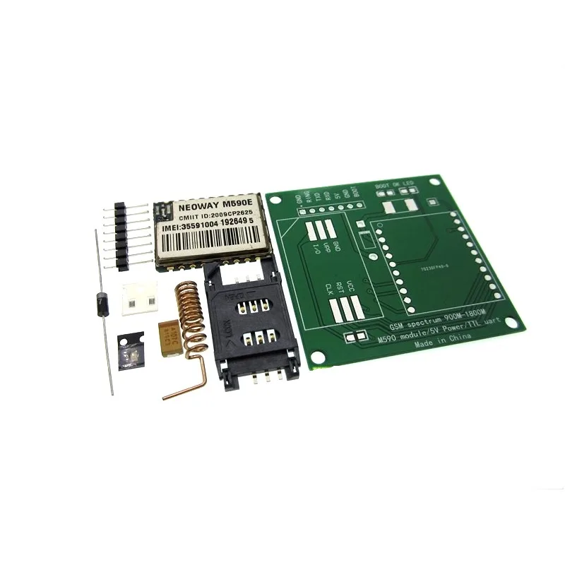
DIY GSM/GPRS M590E Module Kit
M590E-based GSM/GPRS module kit — lower peak current demand than SIM800L makes it slightly more forgiving on power supply. Includes everything needed to build your own GSM node.

15cm 3DBI GSM/GPRS/3G PCB Antenna with IPEX Connector
A proper antenna improves signal quality and reduces the output power the module needs, which directly lowers peak current draw and reduces reset probability.

1 Channel 12V 30A Relay Module with Optocoupler
For GSM-controlled switching applications — this optocoupler-isolated relay module is controlled by your Arduino and keeps high-current loads safely separated from the microcontroller circuit.
Frequently Asked Questions
Q: My SIM800L works fine with a bench power supply but resets on battery. Why?
Battery internal resistance is not zero. A depleted or cheap LiPo cell can have 200–500 mΩ internal resistance. At 2A burst: 2A × 500 mΩ = 1V sag — pushing a 3.7V battery terminal voltage down to 2.7V, well below the SIM800L’s 3.4V UVLO threshold. Solution: use a fully charged, good-quality LiPo (check: ESR under 100 mΩ) or add 2200 µF of capacitance at the module to absorb the burst instead of making the battery supply it instantly.
Q: Can I power a SIM800L from a 5V USB power bank?
Not directly — the SIM800L maximum voltage is 4.4V, and 5V will damage it. You need a buck converter between the power bank and the module (set to 4.0V). Also, USB power banks have an automatic shutoff when current drops below ~50 mA (to prevent battery drain from connected-but-idle devices). A SIM800L in idle mode draws only 18 mA — the power bank will shut off. Workaround: add a dummy load of 50 mA (e.g., a 68Ω resistor from 4V to GND) or use a non-automatic-shutoff power supply instead.
Q: My GSM module registers fine but fails when I try to send an HTTP request. Is this a power problem?
Possibly. GPRS data transmission is more sustained than a network registration ping. During GPRS TX, the module maintains higher average power for longer bursts (data payload sends vs. short signalling packets). If registration works but data fails, check: (1) Is the GPRS APN configured correctly? (2) Does the SIM have an active data plan? (3) Monitor voltage during data TX — you need adequate bulk capacitance. Also verify your APN: for Jio, use “jionet”; for Airtel, use “airtelgprs.com”; for Vi (Vodafone-Idea), use “www” or “portalnmms”.
Q: Does signal quality affect power draw? Should I put the antenna closer to a window?
Absolutely, and this is an often-overlooked optimisation. GSM modules use Adaptive Power Control (APC) — the module adjusts TX power based on the signal level the base station reports. In a strong signal area (e.g., near a window), the module may transmit at Class 8 (2W), 6 (1W), or even lower. In a weak signal area (basement, far from window), it transmits at maximum Class 4 (2W for 900 MHz GSM). A better antenna or position near a window directly reduces peak current draw and reset probability. Check signal with AT+CSQ: 20+ is good, 10–15 is marginal, below 10 is poor.
Q: The module resets every time the relay it controls clicks. Is this a power supply issue?
Yes, but a different one. Relay coils are inductive loads — when they de-energise, they produce a large voltage spike (back-EMF) that can couple into the VCC rail and trigger the UVLO. Fix: add a flyback diode (1N4007 or similar) across the relay coil, cathode toward positive, anode toward negative. This clamps the spike. If the relay is driven directly from the Arduino and shares ground with the GSM module, also add 100 µF electrolytic across the relay coil power supply and 100 nF across the relay VCC/GND at the relay module board.
Build Reliable GSM Projects
Shop GSM modules, antennas, relay modules, and power supply components at Zbotic — with fast shipping across India and expert support for makers at every level.


Add comment