
A gimbal stabilizer feels almost magical: a camera balances perfectly in mid-air while the drone pitches and rolls beneath it, yet the video remains perfectly level. That magic is powered by specially designed brushless gimbal motors — electrically and mechanically distinct from the high-speed propulsion motors on the drone arms. Understanding how these motors work not only demystifies the technology but helps you choose the right motor for your own gimbal build.
This guide covers the physics of brushless gimbal motors, explains FOC (Field Oriented Control), decodes KV ratings and winding types, and gives you a practical roadmap for building or upgrading a 2-axis gimbal stabilizer.
What Makes a Gimbal Motor Different
If you’ve seen brushless motors on drone propellers, you might assume any BLDC motor can stabilise a camera. It cannot. Here’s why:
Propulsion BLDC motors are optimised for high speed — they have high KV (thousands of RPM/volt), few pole pairs, and wide power bands. Their control is simple: set a throttle level, run as fast as possible.
Gimbal BLDC motors are optimised for precise position control at near-zero speed. They need to:
- Hold a precise angle against gravity and external disturbances
- React within milliseconds to IMU-detected tilt
- Move smoothly through fractions of a degree (no jerking)
- Do all this silently and with minimal heat generation
To meet these requirements, gimbal motors have:
- Very low KV (100–300 KV) — slow shaft rotation per volt means fine angle control
- High pole pair count (7–22 pole pairs) — more poles = finer electrical step = smoother position interpolation
- High-resistance windings — reduces peak current, generates less heat in near-static operation
- Outrunner design — the bell (outer shell) rotates while the stator is fixed, giving maximum torque radius for the frame size
Brushless Motor Fundamentals
A brushless DC (BLDC) motor consists of:
- Stator: The fixed part containing copper wire wound around iron laminations. In a 3-phase motor, the coils are arranged in 3 groups (phases: U, V, W) 120° apart electrically.
- Rotor: The rotating part containing permanent magnets. In outrunners, this is the outer bell shell lined with magnets.
- No brushes or commutator: Unlike DC brushed motors, the current switching is done electronically by the controller (ESC or gimbal driver) — which is why it’s called “brushless.”
How Rotation is Created
The controller energises each of the 3 phases in sequence, creating a rotating magnetic field in the stator. This rotating field pulls the permanent magnets in the rotor along, creating torque. The sequence must stay synchronised with rotor position — which is why gimbal controllers need encoder or back-EMF feedback to track angle.
Why Outrunner Motors for Gimbals
In an inrunner motor, the rotor spins inside the stator — like most hobby motors and fans. In an outrunner, the magnets are on the outside bell, and the stator is inside. Outrunners have a larger moment arm for the magnetic force, producing more torque per watt at low speed. For a gimbal axis that must hold a camera against gravity without overheating, this torque advantage is critical.
KV Rating and Gimbal Motors
KV means RPM per volt of no-load back-EMF — essentially how fast the motor spins per volt applied. For gimbal stabilisers:
- 140–200 KV: Used in heavy-load gimbals (DSLR cameras, 400g+ payloads). High torque, low speed. The 2805 140KV motor is a classic example — it generates large holding torque at 12V battery voltage.
- 200–300 KV: Used in medium gimbals (mirrorless cameras, GoPro-style payloads 100–300g). The 2204 260KV is popular in this range.
- 300–500 KV: Light gimbals, small action cameras, smartphone gimbals.
Why Low KV Matters
Consider a 260KV motor running on 12V. No-load speed = 260 × 12 = 3120 RPM. But in a gimbal, you’re controlling position, not running at top speed. The controller rapidly switches current to hold a specific angle. Low KV means that for a given voltage pulse, the motor moves only a small angular distance — giving the controller finer resolution over position. A 2600KV motor would overshoot wildly before the controller could react.
Field Oriented Control (FOC) Explained
The secret behind smooth gimbal motion is Field Oriented Control — an advanced motor control algorithm used in all modern gimbal controllers (SimpleBGC, Alexmos, ODrive, SimpleFOC).
Traditional BLDC Control vs FOC
Traditional BLDC control (trapezoidal/6-step commutation) switches motor phases in 6 discrete steps per electrical revolution. At each step, the current in one phase jumps abruptly. This causes:
- Torque ripple — the motor “jerks” slightly with each commutation step
- Audible noise at commutation frequency
- Difficulty holding precise angles between steps
FOC instead decomposes motor current into two components:
- d-axis current (Id): Magnetising current aligned with the rotor magnet flux — produces no torque, only controls flux.
- q-axis current (Iq): Torque-producing current, perpendicular to rotor flux — this is what makes the motor turn.
By controlling Id and Iq independently (using Clarke and Park transforms, then PI controllers), FOC maintains maximum torque per ampere and generates a truly rotating (sinusoidal) magnetic field. The result: near-zero torque ripple, silent operation, and precise angle control — exactly what a camera gimbal needs.
FOC Requirements
FOC needs to know rotor position continuously. This is typically provided by:
- Hall sensors (coarse, 6 positions per revolution electrically)
- Magnetic encoder (AS5600/AS5048A — 12–14 bits, smooth and accurate)
- Back-EMF estimation (sensorless FOC — works at moderate speed but not at zero-speed holding, so not used in gimbals)
For gimbal applications, magnetic encoders are standard — one small IC and a disc magnet on the shaft provide the high-resolution feedback FOC needs to hold position at rest.
2-Axis Gimbal Architecture
A 2-axis gimbal stabilises roll (camera tilting sideways) and pitch (camera tilting forward/backward). Yaw (panning left/right) is usually left free or handled by a 3-axis gimbal’s third motor.
Axis Assignment
- Roll motor: Outermost frame, heaviest duty, must counter the full weight of the camera + inner frame. Typically a larger motor (2806/3110 size for DSLR gimbals).
- Pitch motor: Inner frame, lighter duty, only supports the camera itself. Can be a smaller motor (2204/2206 size).
IMU Placement
The IMU (Inertial Measurement Unit — typically a 6-axis MPU-6050 or 9-axis ICM-42688) is mounted on the camera plate. It measures angular velocity (gyroscope) and acceleration (accelerometer). The gimbal controller integrates gyroscope data to detect tilt, then commands the motors to counter-rotate and cancel the motion within milliseconds.
Balancing
Before any electronic stabilisation can work, the gimbal must be mechanically balanced — the camera’s centre of gravity must align with each rotation axis. An imbalanced gimbal makes the motors fight constant gravitational torque, wasting power and reducing stability performance. Proper balancing can take 15–30 minutes but dramatically improves results.
Winding Count and Pole Pairs
The stator slot count and rotor pole count determine the motor’s electromagnetic stepping resolution — essentially the smallest angle the motor can be digitally controlled to.
Common Gimbal Motor Configurations
- 9N12P (9 stator slots, 12 poles = 6 pole pairs): Most common in small-to-medium gimbals. 6 pole pairs × 6 commutation steps = 36 electrical steps per revolution in trapezoidal mode; FOC can interpolate continuously.
- 12N14P: Higher pole count, more torque density, used in heavy-lift gimbals.
- 24N22P: Very high pole count, very smooth — used in cinema gimbal heads and robotic joints.
For DIY builders, knowing N and P isn’t critical for operation — just match the motor to the KV and physical size recommendations for your payload. The gimbal controller auto-detects or allows you to configure pole pairs in its software.
IMU and Encoder Feedback
A complete gimbal stabilisation loop uses two feedback paths:
- IMU → controller: Detects disturbance (helicopter vibration, hand shake). The gyroscope provides high-bandwidth (1kHz+) angular rate data. The controller uses a PID loop to generate a correction angle command for each gimbal axis.
- Encoder → motor driver: Verifies the motor has reached the commanded angle. The FOC algorithm uses the encoder reading (not the IMU) to close the inner current/position loop at high frequency (8–32kHz).
The outer loop (IMU PID) runs at 1–4kHz. The inner loop (FOC current control) runs at 8–32kHz. This nested loop structure is what enables the gimbal to be simultaneously fast (reacting to vibrations in under 1ms) and precise (holding angle to within 0.01°).
Choosing a Gimbal Motor
Use this payload-to-motor selection guide:
| Payload Weight | Camera Examples | Recommended KV | Motor Size |
|---|---|---|---|
| < 50g | Runcam, Caddx FPV cam | 400–600 KV | 1804 / 2204 |
| 50–200g | GoPro Hero, action cam | 200–300 KV | 2204 / 2206 |
| 200–600g | Sony ZV-E10, mirrorless | 100–200 KV | 2804 / 2805 |
| > 600g | DSLR, cinema cameras | 80–140 KV | 3108 / 3510 |
Other Factors
- Stator diameter: The first 2 digits of the size code (e.g., 22xx = 22mm stator diameter). Larger diameter = more torque.
- Stator height: The last 2 digits (e.g., xx04 = 4mm stator height). Taller = more copper = more power handling.
- Cable length: Gimbal motors often come with pre-terminated cables. For drone gimbals, 30cm is standard; for handheld gimbals on longer arms, 50cm may be needed.
Gimbal Controller Boards
The motor alone is only half the system. You need a gimbal controller to run FOC and the stabilisation algorithm:
- SimpleBGC (Alexmos): Most popular DIY board. 2-axis and 3-axis versions. Excellent software (GUI tuning). Open source compatible. ₹2000–₹6000 depending on version.
- Storm32 BGC: Open source, cheaper alternative to SimpleBGC. Good community support.
- ODrive: Open source FOC controller for any brushless motor — more flexible but steeper learning curve. ₹5000–₹15000.
- SimpleFOC + Arduino: For learning and custom builds. The SimpleFOC library supports FOC on Arduino-compatible MCUs. ₹500–₹2000 for components.
Recommended Products from Zbotic
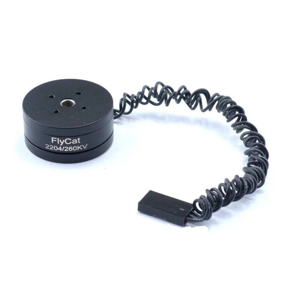
2204 260KV Brushless Gimbal Motor (30cm cable)
The most popular gimbal motor size — ideal for GoPro-class action cameras and lightweight mirrorless builds. Comes with 30cm pre-terminated leads.
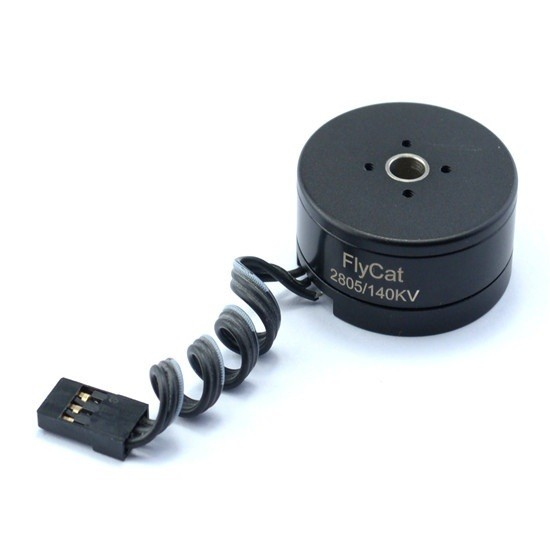
2805 140KV Gimbal Brushless Motor
Higher torque motor for mirrorless or compact DSLR payloads. The 140KV rating and 28mm stator deliver solid holding torque for heavier camera builds.
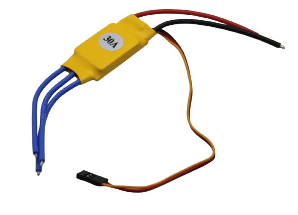
30A BLDC ESC Brushless Electronic Speed Controller
For drone propulsion motors alongside your gimbal — pair a quality ESC with your gimbal motors for a complete drone + stabiliser build.
FAQ
Can I use a drone propulsion motor as a gimbal motor?
No. Propulsion motors have KVs of 1000–3000, far too high for position control. They’re also wound with fewer turns (lower inductance) optimised for high-speed torque, not low-speed holding torque. Using a propulsion motor in a gimbal will result in unstable, jerky behaviour that no amount of PID tuning will fix.
What is the difference between 2204 and 2206 gimbal motors?
The last two digits indicate stator height in mm. A 2204 has a 4mm stator; a 2206 has a 6mm stator. The 2206 packs more copper for the same diameter, resulting in higher torque and lower winding resistance. Choose 2206 for heavier payloads or if you want a cooler-running motor.
How many watts does a gimbal motor use?
At rest (holding position), a well-balanced gimbal draws 100–400mA per motor at 12V — roughly 1.2–4.8W per axis. An unbalanced gimbal fighting gravity can draw 2–5× more. With 3 axes, total consumption is typically 5–15W for a medium gimbal — manageable on a small 2S or 3S LiPo battery.
Why does my gimbal motor get hot?
Usually poor mechanical balance (motor fighting gravity constantly), overly aggressive PID gains (motor hunting and overcorrecting), or too-high motor current settings in the controller. Check balance first, then reduce controller gains until oscillation stops.
Can I use a gimbal motor for a robotic joint?
Yes — this is increasingly common. Gimbal motors offer high torque at low speed and work seamlessly with FOC controllers like SimpleFOC or ODrive for position-controlled robotic joints. They’re used in quadruped robots, robotic arms, and pan-tilt heads.
What cable length do I need for a drone gimbal?
For a standard DJI-style drone gimbal mount, 30cm per motor is usually sufficient. For handheld rig gimbals where the motor is further from the controller board, 50cm is safer. The 2204 260KV motor from Zbotic ships with 30cm cables.
Ready to build your gimbal? Start with the right motors from Zbotic’s brushless motor collection. Browse Gimbal Motors at Zbotic — delivered anywhere in India.


Add comment