
Flyback Diode: Protecting Relays and Transistors Explained
If you have ever had a transistor fail mysteriously the moment a relay or motor switched off, a missing flyback diode for relay and transistor protection is almost certainly the cause. Also called a freewheeling diode, snubber diode, or suppressor diode, this single component costing a few rupees can prevent catastrophic damage to your microcontroller, MOSFETs, and BJTs. This guide explains exactly why flyback diodes are needed, how they work, and how to use them correctly in your circuits.
The Inductive Kickback Problem
Every coil of wire — whether it is a relay coil, a motor winding, or an inductor — stores energy in its magnetic field when current flows through it. The fundamental property of an inductor is that it resists changes in current. When you suddenly switch off the current (by turning off a transistor or relay switch), the magnetic field collapses rapidly.
To maintain the current flow, the inductor generates a voltage spike in the opposite polarity. The amplitude of this spike follows the formula:
V = L * (di/dt)
Where L is the inductance and di/dt is the rate of current change. When a transistor turns off in microseconds, di/dt is enormous. A small 12V relay coil can generate a reverse voltage spike of 50V, 100V, or even higher — far exceeding the breakdown voltage of a typical transistor or microcontroller GPIO pin.
This spike is called inductive kickback or back-EMF. Without protection, it destroys the switching device. In Indian hobbyist projects driving relays from Arduino pins via transistors, this is one of the most common causes of board failure.
How a Flyback Diode Works
A flyback diode is placed in parallel with the inductive load, but in reverse — its cathode connects to the positive supply and its anode to the negative side of the coil. Under normal operation (coil energised), the diode is reverse biased and does not conduct. Current flows through the coil, not through the diode.
The instant the switch opens and the coil tries to generate a reverse voltage spike, the diode becomes forward biased. It clamps the voltage across the coil to approximately +0.7V above the supply rail, providing a safe circulating path for the stored energy. The energy dissipates harmlessly as heat in the coil resistance.
Circuit before flyback diode:
VCC (+12V) ---[Relay Coil]--- Collector
                               |
                             [BJT]
                               |
                              GND

When BJT turns OFF: spike can reach -100V at collector -- destroys BJT!
Circuit with flyback diode:
VCC (+12V) ---+---[Relay Coil]--- Collector
              |                    |
             [D] (cathode to VCC) [BJT]
              |                    |
              +--------------------+
                                  GND

When BJT turns OFF: diode clamps spike to VCC + 0.7V -- BJT is safe!
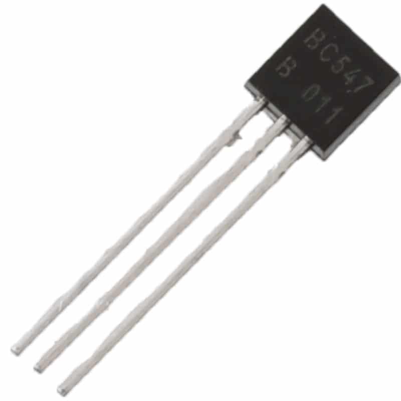
BC547 NPN Transistor TO-92 (Pack of 10)
A classic NPN transistor for relay switching from Arduino. Always pair with a flyback diode across the relay coil to protect the BC547 from inductive kickback.
Flyback Diode for Relay Circuits
Relay coils are the most common inductive load in hobbyist projects. Here is the complete schematic for driving a relay from an Arduino using a transistor with proper flyback protection:
Complete Arduino relay driver circuit:
- Arduino digital pin — 1k base resistor — BC547/2N2222 base
- BC547 collector — relay coil — 12V VCC
- BC547 emitter — GND
- 1N4007 diode: anode to collector end of relay coil (junction of transistor and coil), cathode to VCC
Important points for relay flyback protection:
- Place the diode as physically close to the relay coil terminals as possible — even on the relay module PCB itself
- Long wires between the diode and relay add parasitic inductance, reducing protection
- Most commercial relay modules (5V 1-channel, 2-channel etc.) already have flyback diodes onboard. Check before adding your own
- Use a 1N4007 (1A, 1000V rated) — massively over-specified for the task but dirt cheap and bulletproof
- If using a solid-state relay (SSR), flyback diodes are NOT needed — SSRs have internal protection
Relay coil current check: Before choosing the transistor, calculate the relay coil current. A 5V relay coil rated at 1/4W draws 50mA. A 12V relay at 0.5W draws 42mA. Ensure your transistor’s Ic rating exceeds this with margin (BC547 handles 100mA, 2N2222 handles 600mA).
Flyback Diodes for DC Motor Circuits
DC motors are aggressive inductors. They generate kickback when switching direction, when PWM transitions occur, and even from commutator brush noise during normal operation. A single flyback diode is not enough for a bidirectional motor — you need a full protection scheme.
Single-direction motor (one-way) with low-side switch:
- One flyback diode across the motor terminals (same orientation as relay)
- A 100nF ceramic capacitor directly across the motor terminals (for brush noise suppression)
- Optional: 10nF capacitors from each motor terminal to the motor case/ground
H-bridge bidirectional motor driver:
In an H-bridge (used with L298N, L293D, DRV8833 motor drivers), each transistor/MOSFET switch requires its own flyback diode. That is 4 diodes total. Most integrated motor driver ICs have these built in — check the datasheet before adding external ones.
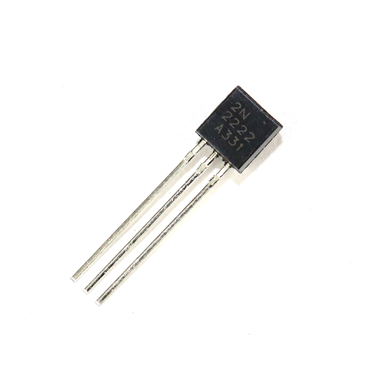
2N2222 NPN Transistor (Pack of 20)
Rated 600mA collector current, the 2N2222 handles heavier relay and solenoid loads than the BC547. Always add a flyback diode when switching inductive loads.
Protecting BJT Transistors
BJT transistors like BC547, BC557, 2N2222, and 2N3906 have an absolute maximum collector-emitter voltage (VCEmax). For BC547, this is 45V. For 2N2222, it is 40V. Inductive kickback can easily exceed these values even on a 5V or 12V circuit.
When the spike exceeds VCEmax, the transistor enters avalanche breakdown. It may survive the first few events, but it degrades each time. Eventually it fails short (collector-emitter short), which typically means the full supply voltage appears on the microcontroller pin, destroying the Arduino or ESP32 as well.
The flyback diode keeps the collector voltage from rising more than 0.7V above the supply rail. For a 12V supply, the maximum the collector sees is 12.7V — well within the transistor’s rating.
How to Choose the Right Flyback Diode
For the vast majority of relay and motor circuits encountered in Indian hobbyist projects, the 1N4007 rectifier diode is the perfect choice:
- Voltage rating: 1000V (PIV) — far more than any hobbyist supply
- Current rating: 1A forward current — adequate for all relay coil currents
- Recovery time: ~4 microseconds — adequate for relay switching speeds
- Cost: A few rupees each — no reason not to use one on every inductive load
When NOT to use 1N4007:
- High-frequency switching (above 20kHz): The 1N4007 is too slow. Use a Schottky diode (1N5819, BAT85) or a fast-recovery diode (1N4148 for low-power) instead. Schottky diodes also have lower forward voltage (0.3V vs 0.7V) which is better in low-voltage systems.
- High-current DC motors (>5A): Use 3A or 10A rated Schottky diodes (SB3100, SR5100)
Correct Placement and Orientation
Orientation is critical — a reversed flyback diode creates a dead short across the power supply. Here is how to get it right every time:
- The diode stripe (cathode marking) always points toward the positive supply (VCC)
- The diode is connected in parallel with the inductive load (relay coil, motor)
- In a low-side switch circuit (transistor to GND): cathode to VCC, anode to the switch node (collector)
- In a high-side switch circuit (transistor to VCC): cathode to the switch node, anode to GND
Physical placement: mount the diode directly across the relay coil pins or motor terminals. Minimise lead length. If the relay is on a separate board connected by long wires, add the diode at the relay end, not the transistor end — the coil generates the spike, so suppress it at the source.
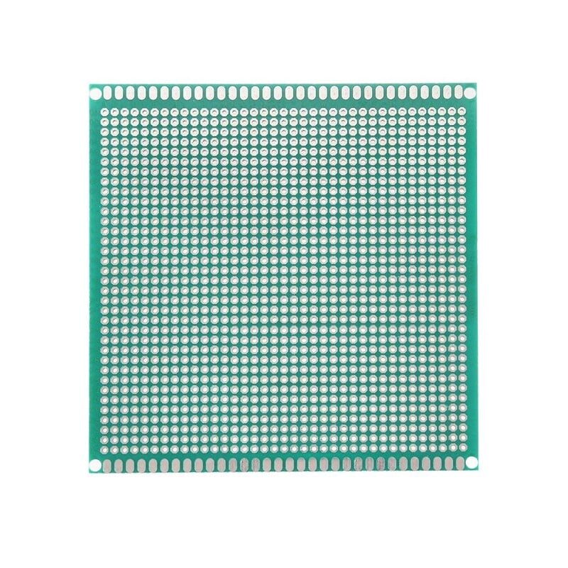
10x10cm Universal PCB Prototype Board
Solder your relay driver circuit with flyback diode permanently on this prototype board. Far more reliable than breadboard for inductive load switching circuits.
Frequently Asked Questions
Does every relay circuit need a flyback diode?
Yes, if you are switching the relay coil with a transistor, MOSFET, or any semiconductor device. The relay coil is an inductor and will generate a reverse voltage spike when switched off. Without a flyback diode, this spike damages or destroys the switching device. Commercial relay modules often include a flyback diode on board — check for a diode next to the relay before adding an external one.
Can I use a 1N4148 instead of 1N4007 for relay protection?
The 1N4148 is a fast-switching signal diode rated at 200mA and 100V. It works for small relay coils (less than 100mA coil current) on 5V or 12V supplies. However, the 1N4007 is rated at 1A and 1000V for the same cost — there is no reason to use 1N4148 for flyback protection. Use 1N4007 as your default for all relay and motor flyback applications.
Why is my flyback diode getting hot?
A flyback diode should barely warm up in normal operation. If it is getting hot, one of three things has happened: (1) the diode is installed backwards and is continuously conducting (a short circuit — remove power immediately); (2) the inductive load is being switched so rapidly (PWM at high duty cycle) that the diode is conducting for extended periods; (3) the diode’s current rating is insufficient for the load current.
Do I need a flyback diode with an L298N or L293D motor driver?
The L293D has built-in flyback diodes (see the datasheet — it has 4 diodes internally). The L298N does NOT have internal flyback diodes — you must add external Schottky diodes (e.g., 1N5819) across the motor terminals. Most L298N modules sold in India include external diodes on the module PCB — check your specific board before adding more.
Can a flyback diode slow down relay response time?
Yes, slightly. When the drive signal is removed, the flyback diode allows the coil current to recirculate (decay slowly through the coil resistance). This can slow relay release time by 1 to 5 milliseconds. For most applications this is irrelevant. If fast relay release is critical (e.g., in timing-sensitive systems), use a Zener diode in series with the flyback diode (Zener + 1N4007 in series) to clamp at a higher voltage and speed up current decay.
Protect Your Projects with Components from Zbotic
Transistors, diodes, resistors, and prototype PCBs — everything you need to build safe relay and motor driver circuits is available at Zbotic. We stock BC547, 2N2222, 1N4007, and more with fast delivery across India.


Add comment