
A DIY exoskeleton hand with flex sensors and servo motors is one of the most impressive and deeply educational robotics projects an Indian maker can build. The concept is simple: when you bend a finger, a flex sensor on your glove detects the bend, sends an analog voltage to an Arduino, and a servo motor on a robotic hand mirrors your movement in real time. The result is a wearable controller that replicates hand gestures — useful for telepresence, prosthetics research, and VR haptic feedback. This guide covers every detail from circuit design to 3D-printed finger assemblies and full Arduino code.
How a Flex-Sensor Servo Glove Works
A flex sensor is a variable resistor that changes resistance when bent. The 2.2″ flex sensor (Spectra Symbol or clone variants) reads approximately 25 kΩ flat and 45–125 kΩ when fully bent. By placing it in a voltage divider with a fixed 47 kΩ resistor, you get a voltage output that varies linearly with bend angle — typically 0.5 V (straight) to 3.5 V (fully bent) on a 5 V system.
The Arduino reads this analog voltage on pins A0–A4 (one per finger), converts it with analogRead() to a 0–1023 value, maps it to a servo angle (0°–180°), and writes the angle to the corresponding servo on the robotic hand. The entire sensing and actuation loop runs in under 20 ms, making the mirroring feel nearly instantaneous.
Full system architecture:
Glove (input side):
  Flex sensors × 5 → Voltage dividers → Arduino A0-A4

Robotic hand (output side):
  Arduino D3,D5,D6,D9,D10 → Servo × 5 → Finger joints
Components List and Cost in India
Here is the complete bill of materials for a 5-finger servo glove exoskeleton. All parts are available from Zbotic or local electronics markets:
| Component | Qty | Approx. Cost (₹) |
|---|---|---|
| Arduino Uno/Mega | 1 | 350–600 |
| SG90 Servo Motors | 5 | 250–400 |
| 2.2″ Flex Sensors | 5 | 400–800 |
| 47 kΩ Resistors | 5 | 10 |
| Servo Mount Brackets | 5 | 100–200 |
| Breadboard / PCB | 1 | 50–150 |
| Jumper wires | Set | 60 |
| Fishing line / Nylon thread | 5 m | 30 |
| Cotton/neoprene glove | 1 pair | 50–100 |
| HC-05 Bluetooth (optional) | 1 | 150–250 |
| Total | ~₹1,500–₹2,500 |
Use Arduino Mega if you plan to add features like an MPU-6050 wrist IMU, pressure sensors in fingertips, or an OLED display — it has more I/O pins and SRAM than the Uno.
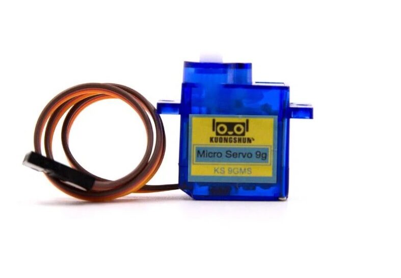
Servo SG90 9g 180 Degree
The SG90 is the standard servo for DIY exoskeleton hand and servo glove projects — lightweight (9g), 180° range, and available at budget-friendly pricing in India.
Flex Sensor Voltage Divider Circuit
Each flex sensor forms a voltage divider with a fixed resistor. The formula for the output voltage:
Vout = Vcc × R_fixed / (R_flex + R_fixed)

Where:
  Vcc = 5V
  R_fixed = 47kΩ
  R_flex = 25kΩ (flat) to 125kΩ (bent)

Vout flat  = 5 × 47/(25+47) = 3.26 V  → analogRead ≈ 667
Vout bent  = 5 × 47/(125+47) = 1.37 V → analogRead ≈ 280
Connect for each finger:
- Connect flex sensor between 5 V and the junction point.
- Connect 47 kΩ between the junction point and GND.
- Connect the junction point to Arduino analog pin A0 (for finger 1), A1 (finger 2), etc.
Important: use separate voltage dividers for each flex sensor. Do not share the 5V line through all flex sensors in series — this would create cross-coupling between fingers.
Calibration Step
Flex sensors vary between units and with temperature. Always run a calibration routine at startup:
// Hold all fingers straight during startup for 2 seconds
// Then curl all fingers fully for 2 seconds
// Arduino records min/max for each sensor automatically
Building the Robotic Hand Structure
The robotic hand can be built in three ways:
Option 1: Ready-Made Acrylic Arm Kit
Use a pre-built acrylic robot manipulator arm with servo mounts. This is the fastest approach — you get the structural frame instantly and just mount servos in the provided brackets.
Option 2: 3D-Printed Tendon-Driven Hand
Print individual finger segments with joints. Each finger has three phalanges (proximal, middle, distal) linked by a single nylon tendon that passes through a channel in each segment. The servo reels in or lets out the tendon to curl/extend the finger. This design is the most anatomically accurate.
Option 3: Servo-Direct Linkage
Mount one servo per finger. Use a rigid linkage rod (stiff wire or 3D-printed rod) from the servo horn directly to the fingertip. Simpler than tendons, but the servo must be positioned near the finger it controls — usually on the back of the hand frame.
For Indian beginners, Option 1 (acrylic kit) or Option 3 (direct linkage with servo brackets) are the fastest to build. Option 2 requires a 3D printer but produces the most impressive result.
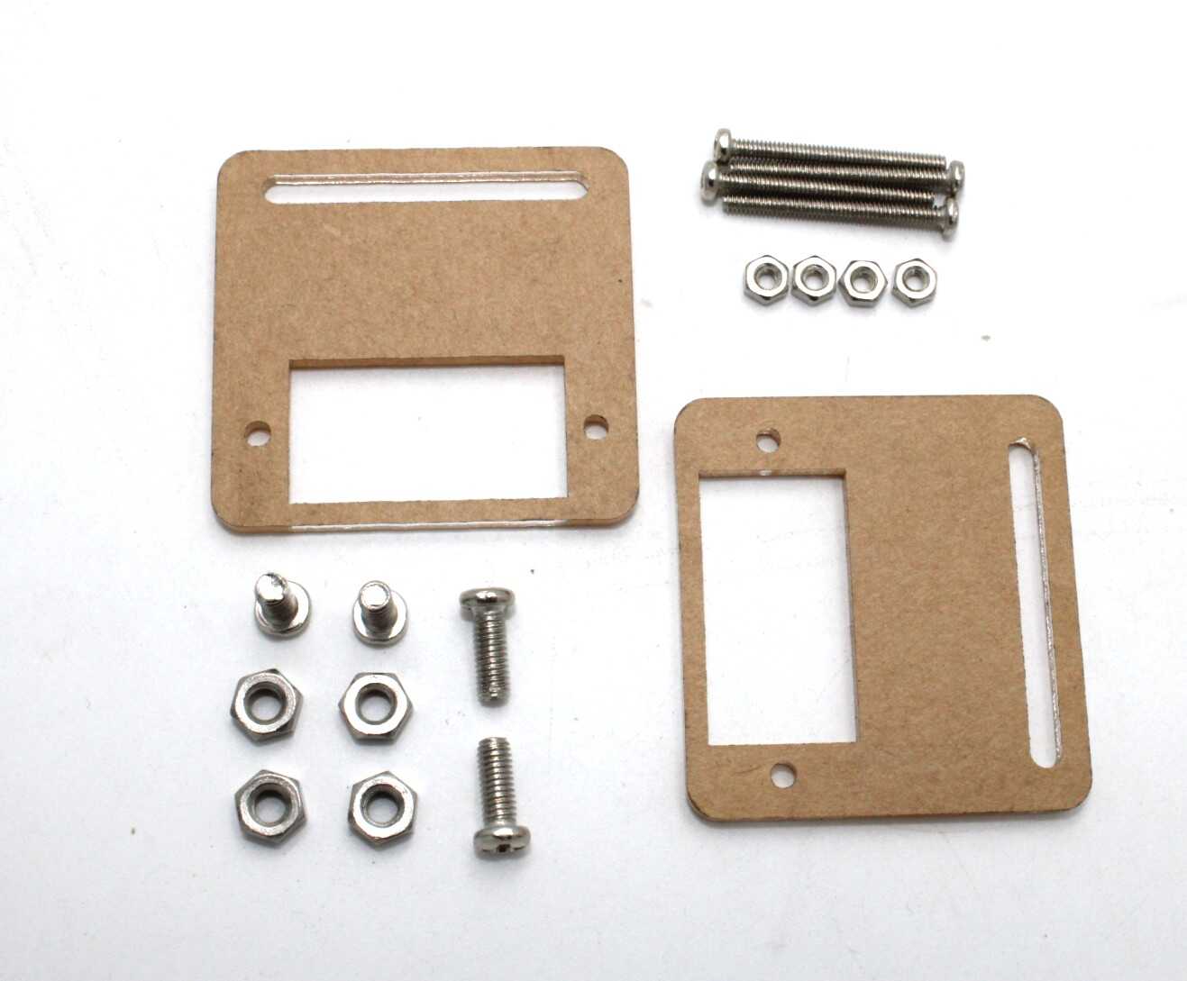
Servo Mount Holder Bracket For SG90/MG90 (Pack of 2)
Rigid servo brackets designed for SG90/MG90 motors — essential for mounting finger servos securely on your robotic exoskeleton hand frame.

DIY Acrylic Robot Manipulator Mechanical Arm Kit
A complete acrylic mechanical arm kit — use as the hand frame for your servo glove project with servo-ready mounting points for all finger actuators.
Arduino Code: Finger Mapping and Calibration
Here is the complete Arduino sketch for a 5-finger servo glove with calibration:
#include <Servo.h>

Servo finger[5];
const int flexPin[5] = {A0, A1, A2, A3, A4};
const int servoPin[5] = {3, 5, 6, 9, 10};
int flexMin[5], flexMax[5];

void setup() {
  for (int i = 0; i < 5; i++) {
    finger[i].attach(servoPin[i]);
    finger[i].write(0); // extend all fingers
  }
  calibrate();
}

void calibrate() {
  // Phase 1: record straight values for 2 seconds
  delay(2000);
  for (int i = 0; i < 5; i++) flexMax[i] = analogRead(flexPin[i]);
  // Phase 2: user curls fingers; record bent values
  delay(3000);
  for (int i = 0; i < 5; i++) flexMin[i] = analogRead(flexPin[i]);
}

void loop() {
  for (int i = 0; i < 5; i++) {
    int raw = analogRead(flexPin[i]);
    int angle = map(raw, flexMin[i], flexMax[i], 180, 0);
    angle = constrain(angle, 0, 180);
    finger[i].write(angle);
  }
  delay(20);
}
This sketch reads each flex sensor, maps it from calibrated min/max values to a 0°–180° servo angle, and updates all 5 servos every 20 ms (50 Hz). The constrain() call prevents the servo from receiving out-of-range commands if a sensor reads outside calibration bounds.
Going Wireless: Bluetooth Glove Control
Adding wireless capability transforms the servo glove from a wired demo into a true teleoperation device. Use the HC-05 Bluetooth module on the glove side (transmitter) and another HC-05 on the robotic hand side (receiver). Configure one as master and the other as slave using AT commands.
Transmitter (glove) Arduino sends 5 angle values over Bluetooth serial:
// Transmitter: send comma-separated angles
Serial.print(angle[0]); Serial.print(',');
Serial.print(angle[1]); Serial.print(',');
// ... up to angle[4]
Serial.println();
Receiver (robotic hand) Arduino parses the comma-separated string and writes angles to servos. Range is approximately 10 metres in line of sight. For longer range, replace HC-05 with an nRF24L01 (100 m indoor) or ESP32 Wi-Fi pair (LAN range).
3D Printing the Exoskeleton Glove Frame
A 3D-printed exoskeleton frame sits on the back of the hand and channels sensor wires cleanly. Key design considerations:
- Print the dorsal (back-of-hand) plate in TPU or flexible PETG so it conforms to hand shape
- Add integrated channels (3 mm wide, 2 mm deep) for flex sensor routing along each finger
- Include snap-in holders for SG90 servos on each finger metacarpal position
- Print at 25–30% infill to reduce weight — this part carries no structural load
- Size the frame parametrically: scale X/Y by hand-length-to-standard-hand ratio
Popular STL resources: search “flex sensor glove frame” on Thingiverse. The “InMoov robot hand” project on Thingiverse includes the most anatomically detailed tendon-driven hand design with full assembly instructions.
Advanced Features: Force Feedback and EMG
Once your basic servo glove works, these enhancements make it significantly more capable:
Force Feedback
Add a small vibration motor (ERM motor, same type as in mobile phones) to each fingertip of the glove. When the robotic hand’s finger encounters resistance (measured by a force-sensitive resistor at the fingertip), the vibration motor on the corresponding glove finger activates. This gives the wearer tactile feedback about what the robot hand is touching.
EMG Control (Next Level)
Instead of flex sensors, use electromyography (EMG) sensors on forearm muscles. The MyoWare 2.0 muscle sensor module connects to the skin surface and outputs an analog voltage proportional to muscle activation. This enables gesture recognition from forearm muscle patterns — meaning you can control the hand without wearing the flex-sensor glove at all.
Wrist Rotation via IMU
Add an MPU-6050 IMU to the glove wrist. Read the yaw angle and map it to a wrist rotation servo on the robotic hand. Now your robotic hand rotates when you rotate your wrist — adding a 6th degree of control on top of the 5 finger DOF.
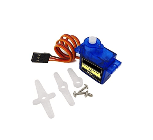
TowerPro SG90 180 Degree Rotation Servo Motor
Genuine TowerPro SG90 servo — the most reliable 9g servo for wrist rotation and finger joint control in your DIY exoskeleton hand project.
Frequently Asked Questions
How many flex sensors do I need for a servo glove?
Five flex sensors — one per finger. Some budget builds use only 4 (combining ring and little finger) or even 3 (thumb, index, combined middle/ring/little) to reduce cost. Five sensors give the most accurate and natural finger-by-finger control.
Can I use the servo glove for a college project in India?
Yes — this is an excellent BTech/diploma final-year project. It covers analog sensing, PWM servo control, calibration algorithms, and optionally wireless communication. Add Bluetooth or Wi-Fi for extra marks, or interface with a Python GUI on a laptop for live finger angle visualisation.
Why is my servo jittering even when I hold my finger still?
Flex sensors are noisy. Add a low-pass filter in code: filtered = 0.8 * filtered + 0.2 * raw (exponential moving average). This smooths the signal without adding noticeable lag. Also ensure your power supply can handle all 5 servos simultaneously — underpowering causes jitter.
What is the difference between exoskeleton and servo glove?
Technically, an exoskeleton hand assists or augments the wearer’s own hand movement (with the robot frame attached to the hand). A servo glove uses the hand as a sensor and controls a separate robotic hand remotely. Most DIY projects called “exoskeleton gloves” are actually servo gloves — the glove only senses, and the robot hand is separate.
Can I add all 5 servos to a single Arduino Uno?
Yes. The Arduino Servo library supports up to 12 servos on an Uno. Use digital PWM pins 3, 5, 6, 9, 10, and 11 for servo control. Power the servo power rail (VCC) from a separate 5V supply — not from the Arduino’s 5V pin, which cannot safely supply more than 400 mA for all servos combined.
Start Building Your Exoskeleton Glove Today
Get SG90 servos, servo brackets, and all the robotics components you need for your DIY exoskeleton hand project from Zbotic — fast delivery across India.


Add comment