
When building high-speed IoT systems in India, one of the most critical skills is mastering ESP32 interrupt UART serial communication. Polling-based serial reading — where your code constantly checks if data is available — works fine for hobby experiments but breaks down the moment you need to handle fast sensor data, GPS streams, or GSM module responses without dropping bytes or freezing the CPU. Interrupt-driven UART solves this by letting the hardware notify your firmware asynchronously when data arrives, freeing the processor to do real work in between. This tutorial covers ESP32 UART architecture, ISR-based reception, ring buffers, and DMA transfers at a depth rarely found in hobbyist guides.
ESP32 UART Hardware Overview
The ESP32 silicon includes three independent hardware UART controllers: UART0, UART1, and UART2. Each UART has its own hardware TX/RX FIFO buffers (128 bytes each by default), baud rate generator, parity checker, and interrupt controller. This is fundamentally different from software-emulated serial (bit-banging) used on AVR-based Arduinos — ESP32 UART is fully hardware-backed, meaning no CPU cycles are wasted generating or sampling individual bits.
Default UART Pin Assignments
| UART Port | Default TX GPIO | Default RX GPIO | Common Use |
|---|---|---|---|
| UART0 | GPIO 1 | GPIO 3 | USB debug / programming |
| UART1 | GPIO 10 | GPIO 9 | Flash (remap for app use) |
| UART2 | GPIO 17 | GPIO 16 | Sensor / GSM / GPS |
The GPIO matrix on ESP32 allows routing any UART TX/RX to almost any GPIO pin, giving you tremendous flexibility. UART0 is occupied by the USB-to-serial chip on DevKit boards, so for application code use UART1 or UART2 with remapped GPIOs.
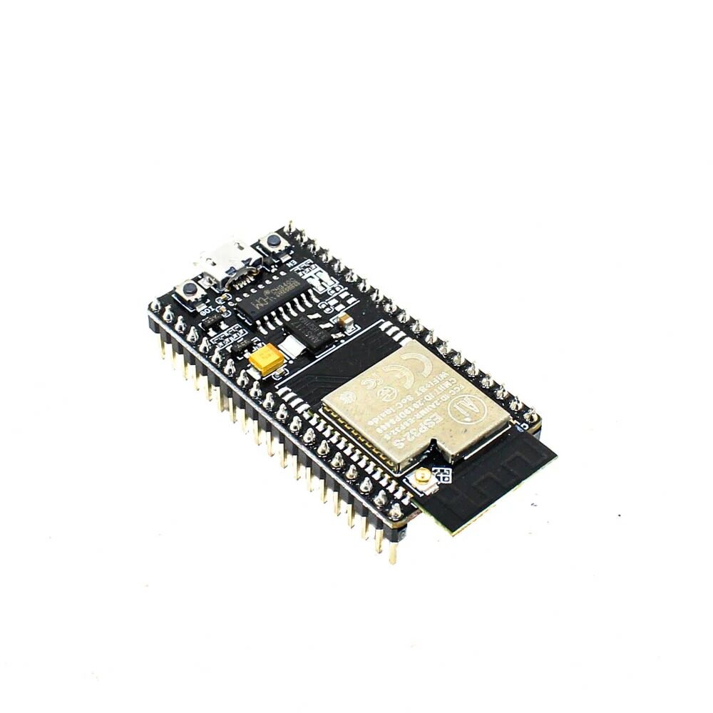
Ai Thinker NodeMCU-32S-ESP32 Development Board – IPEX Version
This ESP32 development board exposes all three UART ports, giving you room to run UART2 for your sensor while UART0 stays free for debug output — essential for interrupt-driven UART projects.
Why Interrupt-Driven UART Beats Polling
In a polling-based design, your main loop constantly calls Serial.available() or uart_read_bytes() and checks if data is ready. This approach has three fatal flaws for production IoT firmware:
- CPU waste: At 115200 baud, a byte arrives every ~87 µs. Between bytes the CPU is spinning in a busy-wait loop, burning power and blocking other tasks.
- Latency variability: If a WiFi event handler, RTOS task scheduler, or sensor read delays the poll loop by even 1–2 ms, you risk overrunning the 128-byte hardware FIFO and losing data permanently.
- Responsiveness: Real-time systems (motor controllers, GPS parsers, GSM AT command handlers) need deterministic byte-level response times that polling cannot guarantee.
With interrupt-driven UART, the UART hardware asserts an interrupt line the moment data arrives in the RX FIFO (or when the FIFO reaches a threshold). The CPU services the ISR (Interrupt Service Routine) immediately, copies bytes into a software ring buffer, and returns to whatever it was doing — typically in under 5 µs. The main application reads from the ring buffer at leisure without any risk of data loss.
ESP-IDF UART Interrupt Setup
The ESP-IDF UART driver internally uses interrupts and an event-driven task model. Here is the canonical pattern for interrupt-driven UART RX in ESP-IDF:
#include "driver/uart.h"
#include "freertos/FreeRTOS.h"
#include "freertos/task.h"
#include "freertos/queue.h"

#define UART_NUM       UART_NUM_2
#define TX_PIN         17
#define RX_PIN         16
#define BUF_SIZE       1024
#define UART_BAUD      115200

static QueueHandle_t uart_queue;

void uart_event_task(void *pvParameters) {
    uart_event_t event;
    uint8_t buf[BUF_SIZE];
    for (;;) {
        if (xQueueReceive(uart_queue, &event, portMAX_DELAY)) {
            if (event.type == UART_DATA) {
                int len = uart_read_bytes(UART_NUM, buf, event.size, pdMS_TO_TICKS(100));
                // Process buf[0..len-1] here
            }
        }
    }
}

void app_main(void) {
    uart_config_t cfg = {
        .baud_rate = UART_BAUD,
        .data_bits = UART_DATA_8_BITS,
        .parity    = UART_PARITY_DISABLE,
        .stop_bits = UART_STOP_BITS_1,
        .flow_ctrl = UART_HW_FLOWCTRL_DISABLE
    };
    uart_param_config(UART_NUM, &cfg);
    uart_set_pin(UART_NUM, TX_PIN, RX_PIN, UART_PIN_NO_CHANGE, UART_PIN_NO_CHANGE);
    uart_driver_install(UART_NUM, BUF_SIZE * 2, BUF_SIZE * 2, 20, &uart_queue, 0);
    xTaskCreate(uart_event_task, "uart_task", 4096, NULL, 12, NULL);
}
The uart_driver_install call with the queue handle is what activates interrupt-driven mode. The ESP-IDF UART driver installs a hardware ISR that fills an internal ring buffer and posts UART_DATA events to your queue. Your task wakes up only when data is available — zero polling overhead.
Using Ring Buffers for Safe ISR Data Transfer
A ring buffer (also called a circular buffer) is the canonical data structure for transferring bytes from an ISR to application code safely. The ISR writes to the buffer; the application reads from it. Because the ISR and app code run in different contexts, the buffer implementation must be lock-free or use critical sections.
Key Ring Buffer Rules for ESP32 ISRs
- Never use heap allocation inside an ISR (
malloc,new). Allocate buffers statically or at init time. - Never call blocking functions from an ISR: no
printf, novTaskDelay, no mutex locks. - Use volatile for shared variables accessed from both ISR and main code:
volatile uint16_t head, tail; - Use
portYIELD_FROM_ISR()at the end of your ISR if you have posted to a FreeRTOS queue inside it, to trigger an immediate context switch to the waiting task. - Keep ISRs short: Copy bytes from FIFO to buffer, update index, yield — done. Never parse or process data inside the ISR.
Arduino Framework: HardwareSerial and Custom ISRs
If you’re using the Arduino framework for ESP32 (via Arduino IDE or PlatformIO), the HardwareSerial class already uses interrupt-driven buffering internally. A 256-byte ring buffer receives bytes via the UART RX interrupt automatically. However, the default buffer size may be insufficient for high-baud-rate sensors like GPS modules streaming NMEA at 9600–38400 baud.
Increasing the Arduino UART Buffer Size
In your project’s platformio.ini or Arduino IDE board settings, set:
build_flags = -DRXBUFFERSIZE=2048Or in Arduino IDE, edit the HardwareSerial.h file and change SERIAL_RX_BUFFER_SIZE. Alternatively, use the Serial2.setRxBufferSize(2048) method available in ESP32 Arduino core 2.x.
Using Serial2 with Custom Pins
// In setup():
Serial2.begin(9600, SERIAL_8N1, 16, 17); // RX=16, TX=17
Serial2.setRxBufferSize(2048);

// In loop():
while (Serial2.available()) {
    char c = Serial2.read();
    // Process character
}
This is interrupt-driven behind the scenes — Serial2.available() just reads the ring buffer head/tail pointers without any hardware polling.

30Pin ESP32 Expansion Board with Type-C and Micro USB
The clearly labelled GPIO breakout on this expansion board makes it easy to route UART2 TX/RX pins to external sensors or GSM modules without jumper wire confusion.
Multi-UART: Using All Three UART Ports
ESP32’s three UART ports let you run multiple serial devices simultaneously — something the single-UART Arduino Uno famously cannot do without software serial hacks. A typical real-world ESP32 serial topology:
- UART0 (GPIO 1/3): USB debug serial — Serial Monitor output during development.
- UART1 (remapped to GPIO 4/5): GSM/4G LTE modem (AT commands) — interrupt-driven, 115200 baud.
- UART2 (GPIO 16/17): GPS module (NMEA stream) — interrupt-driven, 9600 baud.
To remap UART1 away from the flash pins (GPIO 9/10, which you must NOT use on most modules), call:
Serial1.begin(115200, SERIAL_8N1, 4, 5); // RX=GPIO4, TX=GPIO5With all three UARTs running interrupt-driven, your loop() can run application logic — MQTT publish, HTTP POST, display updates — while serial data from GPS and GSM accumulates safely in their respective ring buffers.
DMA-Driven UART for Maximum Throughput
For extremely high baud rates (921600 baud and above) or when processing thousands of bytes per second, even interrupt-driven reception creates overhead because each byte triggers a separate ISR invocation. DMA (Direct Memory Access) solves this by letting the UART hardware write directly to a RAM buffer without any CPU involvement — the CPU is only notified once the buffer is full or a timeout occurs.
ESP-IDF UART driver supports DMA in ESP32-S3 targets. For original ESP32, the uart_driver_install API with a sufficiently large RX buffer achieves near-DMA efficiency because the internal ringbuf is fed via a combined FIFO-threshold + RX-timeout interrupt strategy — bytes are batched, not individually interrupted.
For the highest performance on standard ESP32, set a high FIFO threshold:
uart_intr_config_t intr_cfg = {
    .intr_enable_mask = UART_RXFIFO_FULL_INT_ENA | UART_RXFIFO_TOUT_INT_ENA,
    .rxfifo_full_thresh = 120,    // Interrupt when FIFO has 120 bytes
    .rx_timeout_thresh = 10,      // Interrupt after 10-char idle time
};
uart_intr_config(UART_NUM_2, &intr_cfg);
This reduces interrupt frequency by ~120x compared to per-byte interrupts, dramatically cutting ISR overhead at high baud rates.
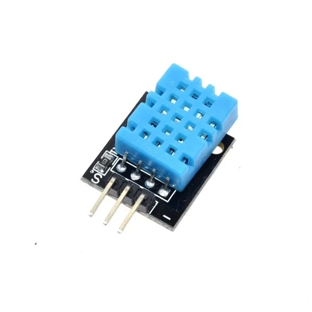
DHT11 Digital Temperature and Humidity Sensor Module
Pair your interrupt-driven UART ESP32 project with the DHT11 for environmental monitoring — combine UART-based GSM reporting with local temperature/humidity sensing in one build.
Frequently Asked Questions
Can I use UART1 on ESP32 for my sensor since UART0 is used by USB?
Yes, but GPIO 9 and 10 (default UART1 pins) are connected to the SPI flash on most ESP32 modules — using them will crash the chip. Always remap UART1 to safe GPIOs like 4/5 or 25/26 using the custom pin argument in Serial1.begin(baud, config, rx_pin, tx_pin).
How do I detect the end of a UART message in an ISR?
ESP32 UART has a built-in RX idle timeout interrupt (RXFIFO_TOUT). Configure it via uart_intr_config with a timeout of 3–10 character periods. When the line goes idle (no new bytes) for that duration, an interrupt fires signalling end-of-packet. This is the standard way to implement message framing without explicit delimiters.
My ISR-based UART is dropping bytes at 921600 baud. What’s wrong?
At 921600 baud, a byte arrives every ~10.8 µs — faster than most ISR round-trips if WiFi or BT interrupt handlers are also running. Solutions: disable WiFi while receiving (if not needed simultaneously), increase FIFO threshold to batch bytes per interrupt, or switch to ESP32-S3 which supports true UART DMA.
Is interrupt-driven UART safe to use with FreeRTOS on ESP32?
Yes — and it’s the recommended pattern. Use xQueueSendFromISR() and portYIELD_FROM_ISR() to communicate from ISR to tasks. Never call any non-ISR-safe FreeRTOS API (those without FromISR suffix) from inside an interrupt handler.
Get ESP32 Boards and Sensor Modules at Zbotic
Build your interrupt-driven UART project with ESP32 development boards, sensors, and expansion boards available at Zbotic.in — India’s trusted electronics components store with fast shipping nationwide.


Add comment