
Using an ESP32 I2C scanner to find unknown sensor addresses is the fastest way to solve one of the most common hardware headaches in embedded development. You wire up a new sensor, write your code with the datasheet-specified address, upload — and nothing works. The sensor is silent. Is the address wrong? Is the wiring off? Is the sensor broken? An I2C scanner resolves all of these questions in under 60 seconds. This guide explains the protocol fundamentals, provides a complete scanner sketch, and walks through diagnosing every common I2C problem on ESP32.
I2C Protocol Basics for ESP32
I2C (Inter-Integrated Circuit) is a two-wire serial communication protocol using a clock line (SCL) and a data line (SDA). Every device on the I2C bus has a 7-bit address (0x00–0x7F), though the full 128-address space is not all usable — addresses 0x00–0x07 and 0x78–0x7F are reserved. In practice, most sensors use addresses in the range 0x08–0x77, giving 112 possible device addresses.
On ESP32, I2C is handled by the Wire library. The default I2C pins on most ESP32 boards are:
- SDA: GPIO 21
- SCL: GPIO 22
However, one of the ESP32’s most powerful features is that almost any GPIO can be reassigned as SDA or SCL using the Wire.begin(SDA_PIN, SCL_PIN) call. This flexibility is critical for custom PCB designs and boards where the default pins are occupied.
I2C uses open-drain signaling, which means both SDA and SCL lines must have pull-up resistors to VCC. Most sensor modules and breakout boards include on-board pull-up resistors (usually 4.7kΩ or 10kΩ), so for quick prototyping you often do not need external ones. However, when connecting multiple I2C devices, too many parallel pull-ups can lower the effective resistance below 1kΩ, causing signal integrity issues at higher speeds.
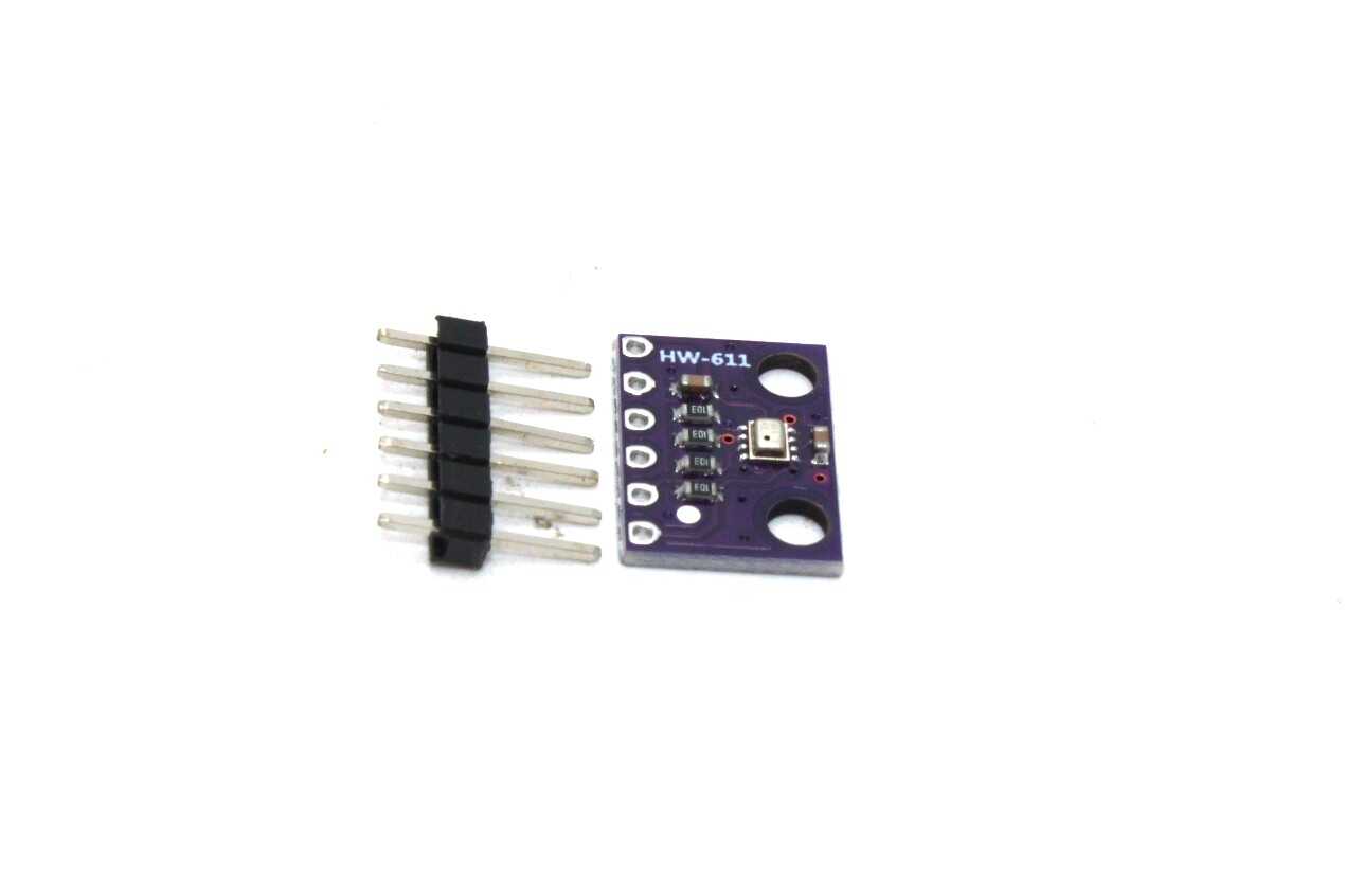
BMP280 Barometric Pressure and Altitude Sensor I2C/SPI Module
A popular I2C sensor available at address 0x76 or 0x77 — use the scanner to confirm which address your specific module uses before writing any code.
The Complete ESP32 I2C Scanner Sketch
Here is a comprehensive I2C scanner that covers all 112 valid addresses, reports found devices clearly, and handles errors gracefully. Upload this as-is to any ESP32 board:
#include <Wire.h>

// Change these if your board uses different I2C pins
#define SDA_PIN 21
#define SCL_PIN 22

void setup() {
  Serial.begin(115200);
  delay(1000); // Wait for Serial to init

  Wire.begin(SDA_PIN, SCL_PIN);
  Wire.setClock(100000); // 100 kHz standard mode

  Serial.println("nn=== ESP32 I2C Scanner ===");
  Serial.print("SDA: GPIO "); Serial.println(SDA_PIN);
  Serial.print("SCL: GPIO "); Serial.println(SCL_PIN);
  Serial.println("Scanning from 0x01 to 0x7F...");
  Serial.println();

  scanI2C();
}

void scanI2C() {
  byte error;
  byte address;
  int deviceCount = 0;

  for (address = 1; address < 127; address++) {
    Wire.beginTransmission(address);
    error = Wire.endTransmission();

    if (error == 0) {
      Serial.print("Device found at: 0x");
      if (address < 16) Serial.print("0");
      Serial.print(address, HEX);
      Serial.print(" (");
      Serial.print(address);
      Serial.print(") → ");
      Serial.println(getDeviceName(address));
      deviceCount++;
    } else if (error == 4) {
      Serial.print("Unknown error at 0x");
      if (address < 16) Serial.print("0");
      Serial.println(address, HEX);
    }
    delay(10);
  }

  Serial.println();
  if (deviceCount == 0) {
    Serial.println("No I2C devices found!");
    Serial.println("Check wiring and pull-up resistors.");
  } else {
    Serial.print(deviceCount);
    Serial.println(" device(s) found.");
  }
}

String getDeviceName(byte address) {
  switch (address) {
    case 0x20: case 0x21: case 0x22: case 0x23:
    case 0x24: case 0x25: case 0x26: case 0x27:
      return "PCF8574 I2C GPIO Expander (or PCF8574A at 0x38-0x3F)";
    case 0x3C: case 0x3D:
      return "SSD1306/SSD1315 OLED Display";
    case 0x40: return "PCA9685 PWM Driver or INA219 Current Sensor";
    case 0x44: case 0x45:
      return "SHT31 Temperature & Humidity Sensor";
    case 0x48: case 0x49: case 0x4A: case 0x4B:
      return "ADS1115 ADC or TMP48 Temp Sensor";
    case 0x57: return "MAX30105 Pulse Oximeter";
    case 0x5A: case 0x5B:
      return "MLX90614 IR Thermometer or CCS811 Gas Sensor";
    case 0x68: case 0x69:
      return "MPU-6050/9250 IMU or DS3231/DS1307 RTC";
    case 0x76: case 0x77:
      return "BMP280/BME280 Pressure/Humidity Sensor";
    default:
      return "Unknown Device";
  }
}

void loop() {
  // Rescan every 10 seconds
  delay(10000);
  Serial.println("n--- Rescanning ---");
  scanI2C();
}
Open Serial Monitor at 115200 baud. You will see output like:
=== ESP32 I2C Scanner ===
SDA: GPIO 21
SCL: GPIO 22
Scanning from 0x01 to 0x7F...

Device found at: 0x3C (60) → SSD1306/SSD1315 OLED Display
Device found at: 0x76 (118) → BMP280/BME280 Pressure/Humidity Sensor
Device found at: 0x68 (104) → MPU-6050/9250 IMU or DS3231/DS1307 RTC

3 device(s) found.
Wiring I2C Sensors to ESP32
Correct wiring is the most common reason the scanner finds nothing. Follow these rules:
Voltage levels: ESP32 GPIO pins are 3.3V. If your sensor module has a voltage regulator on-board (most breakout boards do), you can supply it with 3.3V or 5V depending on the module’s VCC range. However, SDA and SCL signal lines must always be at 3.3V levels when connected directly to ESP32. Most modern sensor modules (BME280, MPU-6050, BMP280) operate at 3.3V and are directly compatible. Some older 5V sensors require a logic level shifter on the I2C lines.
Pull-up resistors: For standard 100kHz I2C with one or two sensors on a breadboard, the on-board pull-ups on sensor modules are usually sufficient. If you are having issues, explicitly add 4.7kΩ resistors from SDA to 3.3V and SCL to 3.3V on your breadboard.
Cable length: I2C is designed for short-range communication (same PCB or within a few centimetres). Cables longer than 30cm at 100kHz or 10cm at 400kHz cause signal degradation. Use shielded cables or dedicated I2C bus extenders (like PCA9600) for longer runs.
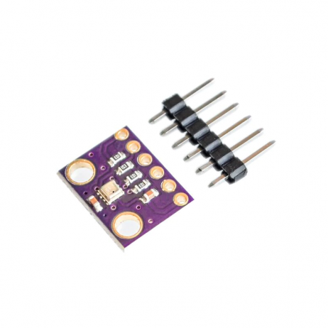
GY-BME280-3.3 Precision Altimeter Atmospheric Pressure Sensor Module
The BME280 combines temperature, pressure, and humidity on I2C/SPI — one of the most popular sensors to scan for in multi-sensor projects.
Common I2C Sensor Address Reference Table
| Sensor / Module | Default Address | Alternate Address | How to Change |
|---|---|---|---|
| BMP280 / BME280 | 0x76 | 0x77 | SDO pin → VCC |
| MPU-6050 | 0x68 | 0x69 | AD0 pin → VCC |
| SSD1306 OLED | 0x3C | 0x3D | SA0 resistor on PCB |
| DS3231 RTC | 0x68 | Fixed | Not configurable |
| ADS1115 ADC | 0x48 | 0x49, 0x4A, 0x4B | ADDR pin → GND/VCC/SDA/SCL |
| PCF8574 GPIO | 0x20 | 0x20–0x27 | A0, A1, A2 pins |
| SHT31 | 0x44 | 0x45 | ADDR pin → VCC |
| INA219 Current | 0x40 | 0x41–0x4F | A0, A1 pins |
Scanning Multiple I2C Buses on ESP32
The ESP32 has two hardware I2C controllers (I2C0 and I2C1), allowing two completely independent I2C buses. This is essential when you have address conflicts — for example, two BMP280 sensors (both fixed at 0x76 or 0x77) needed on the same project:
#include <Wire.h>

#define SDA1 21
#define SCL1 22
#define SDA2 16
#define SCL2 17

TwoWire I2C_1 = TwoWire(0);
TwoWire I2C_2 = TwoWire(1);

void setup() {
  Serial.begin(115200);
  delay(1000);

  I2C_1.begin(SDA1, SCL1, 100000);
  I2C_2.begin(SDA2, SCL2, 100000);

  Serial.println("=== Scanning Bus 1 ===");
  scanBus(I2C_1);

  Serial.println("n=== Scanning Bus 2 ===");
  scanBus(I2C_2);
}

void scanBus(TwoWire &bus) {
  for (byte addr = 1; addr < 127; addr++) {
    bus.beginTransmission(addr);
    if (bus.endTransmission() == 0) {
      Serial.print("Found: 0x");
      if (addr < 16) Serial.print("0");
      Serial.println(addr, HEX);
    }
    delay(5);
  }
}

void loop() {}
You can also use software I2C libraries for a third, fourth bus if needed, though at lower performance.
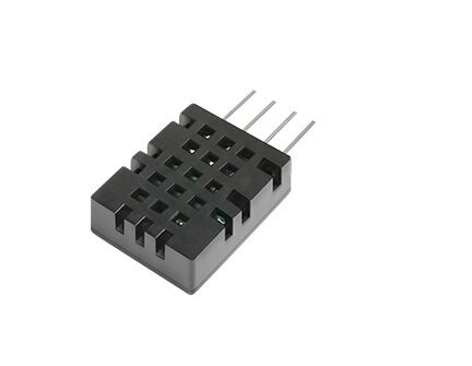
DHT20 SIP Packaged Temperature and Humidity Sensor
Unlike the DHT11/22, the DHT20 communicates via I2C at address 0x38 — scan for it with the ESP32 I2C scanner before initialising the sensor library.
Troubleshooting: No Devices Found
If the scanner reports “No I2C devices found,” work through this checklist:
- Swap SDA and SCL wires — the single most common mistake. Try wiring the sensor’s SDA to GPIO 22 and SCL to GPIO 21 (reversed from default).
- Check VCC — is the sensor powered? A multimeter on the VCC pin of the sensor should show 3.3V.
- Try Wire.begin() without pin args — just
Wire.begin();to use the platform defaults (21, 22 on most boards). - Add explicit pull-ups — wire 4.7kΩ from SDA to 3.3V and SCL to 3.3V on the breadboard.
- Reduce I2C speed — try
Wire.setClock(10000);(10kHz, very slow) to rule out signal integrity issues. - Test the sensor independently — use a 5V Arduino with the sensor to verify the sensor itself is functional.
- Check for address 0x00 — some faulty sensors respond at the general call address. The scanner above starts from 0x01 to avoid this.
Resolving Address Conflicts
When two sensors share the same I2C address, you have three options:
- Use the alternate address — most sensors have at least two selectable addresses via a pin (see table above)
- Use separate I2C buses — as shown in the dual-bus code above, put conflicting sensors on different physical buses
- Use an I2C multiplexer (TCA9548A) — a single chip at address 0x70 that connects to 8 separate I2C channels, each addressable individually. Supports 8x the same sensor with no conflicts
Frequently Asked Questions
Q1. Why does my I2C scanner show a device at 0x00?
Address 0x00 is the I2C general call address. Some poorly designed sensors or counterfeit breakout boards respond to it incorrectly. If you only see 0x00 and nothing else, your wiring or pull-ups are likely the issue — a correct I2C device response at 0x00 is extremely rare.
Q2. Can I use any GPIO as I2C on ESP32?
Almost any GPIO can be used for I2C on ESP32. Avoid GPIO 34, 35, 36, and 39 — these are input-only pins with no internal pull-up capability. You must use external resistors. GPIO 6–11 are connected to the internal flash and must not be used. All other GPIOs are candidates for I2C.
Q3. My MPU-6050 and DS3231 both show at address 0x68 — how do I use both?
The MPU-6050 has an AD0 pin: when pulled LOW it is 0x68, when pulled HIGH it is 0x69. Set AD0 HIGH on the MPU-6050, and place the DS3231 at 0x68. Now both devices have unique addresses. Alternatively, use the dual I2C bus approach and put them on separate buses.
Q4. How do I check if my I2C sensor is 3.3V or 5V compatible?
Check the datasheet for the VIO operating range. Most modern sensors operate at 1.8V–3.6V. The breakout board may have a voltage regulator that accepts 5V on VCC while keeping logic levels at 3.3V — check if the module has a dedicated “3.3V” or “5V” label. When in doubt, use a logic level shifter on the I2C lines when interfacing 5V sensors directly with ESP32.
Q5. What is the maximum number of I2C devices on an ESP32?
Theoretically 112 devices (all valid addresses). Practically, each device adds capacitance to the bus, degrading signal quality. With standard 4.7kΩ pull-ups and 100kHz operation, 8–10 devices is usually the practical limit. Beyond that, use a TCA9548A I2C multiplexer to add up to 8 more buses, effectively allowing 56–80+ devices.
Shop I2C Sensors for ESP32 at Zbotic
Find BMP280, BME280, DHT20, MPU-6050 and dozens more I2C sensors in stock at Zbotic, with fast delivery across India.


Add comment